

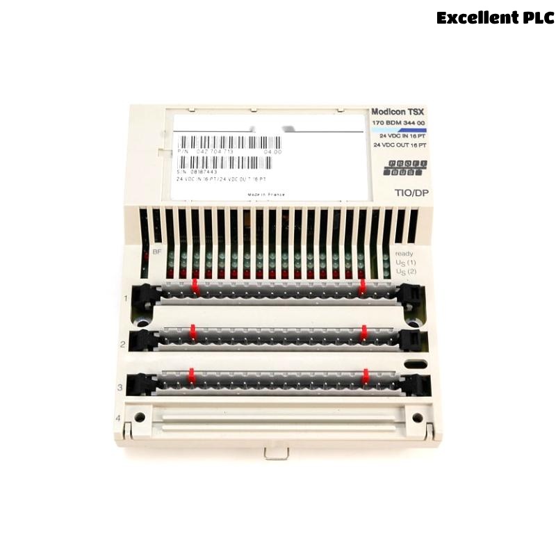
A few months ago, I had to install and commission a Schneider 170BDM34400 Modbus Plus TIO module for a process control panel upgrade. The installation wasn’t particularly difficult, but there were a few critical details that made a big difference in ensuring stable communication and error-free operation. Here’s how the whole process went, step by step, based on my field experience.
Preparing the Installation
Before starting, I made sure the power to the entire PLC rack was turned off. The 170BDM34400 is a Modbus Plus module that connects terminal I/O devices, so any mistake during wiring or installation could lead to communication faults later. I double-checked the wiring diagram and confirmed the module’s slot assignment on the Quantum backplane.
I also verified that the Modbus Plus network was properly terminated and that the node address for the new module had been assigned in advance. This part often gets overlooked, but duplicate addresses can cause serious network instability.
Physical Installation
After verifying everything, I began installing the module:
-
Remove the slot cover on the Quantum I/O base where the module would go.
-
Align the 170BDM34400 module with the guide rails carefully. These modules slide in smoothly if you align them perfectly; forcing them can damage the connectors.
-
Press the module firmly until it clicks into place and the backplane connector is fully seated.
-
Secure the module with the mounting screws at the top and bottom.
Once the module was physically in place, I connected the Modbus Plus cable. For this system, we used Belden 9842 twisted pair cable with proper shielding. I stripped about 1 cm of insulation and connected the blue and clear wires to the MB+ and MB− terminals, ensuring the shield was grounded only at one end to prevent ground loops.
Initial Power-Up and Network Check
After the wiring was complete, I re-energized the PLC rack. The 170BDM34400 module’s LED indicators came on, showing power and network status. I waited a few seconds for the Modbus Plus network to stabilize.
At this point, I checked the LED indicators:
-
STS (Status): Green and steady, meaning the module was running properly.
-
COMM (Communication): Flashing green, indicating active data exchange.
If the COMM light had stayed off, it would have meant a cabling or node address issue, so I always check those LEDs immediately after power-up.
Software Configuration and Commissioning
Next, I moved to the software side. Using Unity Pro (now EcoStruxure Control Expert), I opened the PLC project and confirmed that the slot position matched the physical installation. The software recognized the 170BDM34400 automatically, which confirmed the backplane connection was fine.
I then configured the Modbus Plus node address and communication parameters. I matched the baud rate and parity settings to the existing Modbus Plus network. After downloading the configuration to the PLC, I monitored live data to verify communication with the connected I/O terminals.
During this step, I usually run a loopback test by writing a value to one of the analog outputs and checking if the same value appears in the remote node. This confirms that both transmit and receive functions are working properly.
Troubleshooting and Adjustments
At first, I noticed intermittent communication drops. The COMM LED would blink irregularly, and the PLC occasionally lost connection to one of the I/O stations. After checking the wiring again, I found that one of the Modbus Plus shields was grounded at both ends—causing a small ground loop. Once I lifted the extra ground, communication became perfectly stable.
This is a common issue with Modbus Plus networks, so it’s worth remembering: shielding must be grounded at only one point.
Final Verification
After the network stabilized, I logged data for about an hour to make sure there were no CRC errors or timeouts. The system ran smoothly, all I/O values updated in real time, and the operators could see the correct process signals on the HMI.
I also labeled the module clearly with its node address and installation date for future maintenance. It’s a simple habit, but it saves time later when the system grows or when modules need replacement.
Key Takeaways
-
Always verify slot assignment and node address before installation.
-
Use properly shielded Modbus Plus cable and ground the shield at one point only.
-
Check LED indicators immediately after power-up—they’re your quickest diagnostic tool.
-
Use software to confirm configuration and perform a loopback test to verify data exchange.
-
Document every change for future maintenance.
That installation went smoothly after those adjustments, and the 170BDM34400 module has been running continuously without a single fault ever since. Installing and commissioning Modbus Plus equipment always comes down to careful wiring, grounding, and proper configuration. Small mistakes in these areas can lead to hours of unnecessary troubleshooting, so taking a methodical approach is the best practice.