

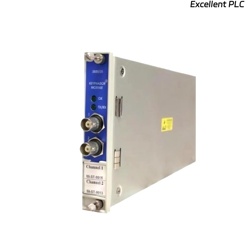
Recently, I installed a Bently Nevada 3500/25-02-03-RU vibration monitoring module on a gas turbine for online shaft monitoring. This module is part of the 3500 series rack system and requires careful handling to ensure accurate signal acquisition. Here’s a step-by-step breakdown based on real-world field experience.
Step 1: Safety and Preparation
-
Power down the 3500 rack and ensure no AC or DC power is applied.
-
Verify the module part number: 3500/25-02-03-RU.
-
Inspect the module and connectors for physical damage or contamination.
-
Prepare tools: torque screwdriver, ESD wrist strap, and multimeter.
Safety first: Even though the 3500 modules are robust, accidental shorts or static discharge can permanently damage sensitive analog circuits.
Step 2: Physical Installation
-
Identify the correct slot in the 3500 rack for the module — usually channel 2 or 3 depending on system configuration.
-
Slide the module gently into the DIN rail guides and ensure it locks into place.
-
Check front LED indicators: initially off, as no power is applied.
Step 3: Wiring the Module
The 3500/25-02-03-RU module typically monitors eddy-current probes or other vibration inputs.
-
Connect signal inputs (IN+) and returns (IN–) to the corresponding channel terminals.
-
Connect the shield/ground to the SG terminal to minimize EMI.
-
Tighten terminals to the manufacturer-recommended torque (~0.4–0.5 Nm).
-
Verify cable continuity using a multimeter before powering up.
Field tip: Loose shield connections are the most common cause of noisy signals in the 3500 system.
Step 4: Power-Up and LED Check
-
Apply power to the 3500 rack.
-
Observe the LED indicators on the module:
-
Green PWR – Module powered correctly.
-
Yellow WARN – Undervoltage or signal anomaly.
-
Red FAULT – Signal lost or internal fault.
-
If a red or yellow LED persists, double-check cable polarity, shield connection, and input voltage levels.
Step 5: System Configuration
After hardware installation, configure the module in the 3500 system software:
-
Assign the module to the correct channel number in the rack.
-
Define the probe type, sampling rate, and alarm thresholds.
-
Verify communication with the central monitoring station.
Step 6: Field Verification with Example Code
Once wired and configured, I usually implement a small Structured Text (ST) logic snippet to validate input signals:
-
This simple code monitors the vibration signal in g’s RMS, flags an alarm if it exceeds operational limits.
-
I often log the output over 1–2 rotations of the shaft to verify consistency.
Step 7: Common Field Issues
From experience, typical installation mistakes include:
-
Incorrect channel assignment → signals appear missing in software.
-
Loose shield or signal connections → noisy readings or intermittent faults.
-
Incorrect probe wiring polarity → negative readings or FAULT LED.
-
Power sequencing errors → module fails to initialize correctly.
Step 8: Best Practices
-
Document module serial number, firmware version, and channel configuration.
-
Perform initial baseline signal capture immediately after installation.
-
Maintain cable routing to prevent mechanical stress and EMI interference.
-
Keep a spare module in the cabinet for rapid replacement in critical systems.
Final Thoughts
The Bently Nevada 3500/25-02-03-RU module is reliable if installed carefully.
Following proper wiring, torque specifications, and software configuration prevents the majority of common startup issues.
“Precision monitoring starts with precise installation — check every wire, secure every connection, and verify every signal.”