

A few months ago, I was tasked with installing a Bently Nevada 70M303 Ranger Pro wireless vibration sensor on a centrifugal compressor in a refinery. Wireless sensors simplify vibration monitoring, but proper installation and linking are crucial for reliable operation. Here’s how I approached it in the field.
Step 1: Pre-Installation Preparation
Before you touch the sensor:
-
Ensure the machine is powered down if you’ll be installing close to moving parts.
-
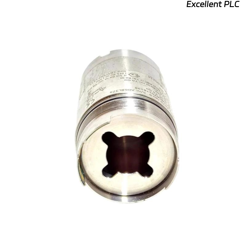
Verify the sensor model: 70M303 Ranger Pro.
-
Charge the sensor fully; these units have a lithium-ion battery that must be at >90% capacity.
-
Prepare the Ranger Pro Gateway or equivalent receiver that collects wireless signals.
-
Gather tools: magnetic base (or threaded mount), cleaning cloth, torque screwdriver, and inspection mirror for tight spaces.
Field tip: A fully charged sensor avoids signal loss during initial linking.
Step 2: Mounting the Sensor
-
Select a stable and flat surface on the bearing housing or machine frame.
-
Clean the area to remove dirt, oil, or scale.
-
Attach the sensor using:
-
Magnetic base for temporary or quick installations.
-
Threaded mount for high-vibration areas — more secure and reduces signal noise.
-
-
Ensure the sensor axis aligns with the vibration direction. Misalignment will produce inaccurate readings.
Step 3: Sensor Activation
-
Press the wake-up button on the Ranger Pro sensor.
-
Observe the LED:
-
Blinking Green: Searching for a network.
-
Solid Green: Awake and ready to link.
-
-
If the sensor does not respond, check battery connection or reset by holding the button for 5–7 seconds.
Step 4: Linking to the Wireless Network
-
Gateway Preparation: Ensure the Ranger Pro Gateway is powered and connected to your monitoring network.
-
Open the Asset Condition Monitoring (ACM) software or Ranger Pro software.
-
Initiate a new sensor discovery session.
-
Press the link button on the sensor once.
-
The sensor should appear as “Unpaired Device.” Assign it a unique ID and set the sampling rate (256 Hz is typical for high-speed machinery).
-
Verify signal strength (RSSI) and battery level. RSSI should be above –80 dBm, and battery >80%.
Field tip: Keep the sensor within line-of-sight range of the gateway during initial linking for best reliability.
Step 5: Verification and Calibration
-
Rotate the shaft slowly if possible, or simulate vibration using a small handheld shaker.
-
Confirm the sensor reports amplitude and frequency correctly.
-
Compare readings with a nearby wired sensor if available for baseline validation.
-
Log the first vibration data for reference in long-term monitoring.
Step 6: Common Field Issues
-
Sensor not discovered:
-
Check battery charge.
-
Move sensor closer to gateway; avoid steel barriers or EMI sources.
-
-
Intermittent readings or low RSSI:
-
Ensure proper mounting; magnetic mounts may slip under high vibration.
-
Verify the gateway is operating on the correct channel and frequency.
-
-
Battery drain:
-
Ranger Pro units discharge faster in extreme temperatures; schedule regular battery checks.
-
Step 7: Best Practices
-
Document sensor ID, location, mounting orientation, and sampling configuration.
-
Use strain relief or cable ties if mounting near moving components.
-
Periodically check battery and link quality in the ACM software.
-
Consider retaining a wired sensor for critical machinery as a reference.
Key Takeaways
-
Correct installation, alignment, and wireless linking ensure reliable vibration monitoring with Ranger Pro sensors.
-
Battery management, line-of-sight placement, and proper configuration prevent common field issues.
-
Baseline verification immediately after installation provides long-term confidence in system readings.
“Wireless convenience is real, but precision and diligence in setup determine whether the data can be trusted.”