

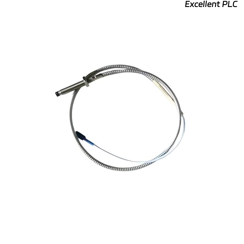
Recently, I installed a Bently Nevada 89477-50 proximity sensor module on a gas turbine bearing housing. These modules are crucial for monitoring shaft position and vibration, and improper installation can cause false readings, trip alarms, or equipment damage. Here’s a detailed, field-tested guide.
Step 1: Pre-Installation Preparation
-
Ensure the machine and monitoring system are powered down.
-
Verify the module part number: 89477-50.
-
Inspect the module for physical damage, bent pins, or contamination.
-
Gather tools: torque screwdriver, multimeter, ESD wrist strap, and cleaning cloths.
Field tip: Proximity sensor modules are sensitive; always wear an ESD wrist strap when handling.
Step 2: Mounting Location
-
Select a stable, vibration-free surface close to the shaft to be monitored.
-
Ensure there is enough clearance for the sensor face and cabling.
-
Clean the mounting surface thoroughly to remove oil, dust, or debris.
-
Mount the module using the OEM-specified screws or brackets, tightening to recommended torque (~0.4–0.5 Nm).
Field insight: Alignment and stability are critical — even a small tilt can affect sensor readings.
Step 3: Module Orientation
-
Align the sensor face perpendicular to the target shaft surface.
-
Maintain the recommended air gap between the sensor and shaft (usually 0.25–1 mm depending on model).
-
Avoid placing the sensor where rotor thermal expansion or vibration could reduce the gap below minimum clearance.
Step 4: Wiring Connections
The 89477-50 module typically has signal and power terminals:
| Terminal | Function | Notes |
|---|---|---|
| +V | Power supply | Follow OEM voltage rating (e.g., 24 VDC) |
| COM | Return / ground | Connect to system common |
| OUT | Sensor signal | Connect to PROXPAC or 3500 monitoring input |
| Shield / PE | Optional protective ground | Maintain shield continuity for noise reduction |
Wiring Steps
-
Strip wires to proper length (~8–10 mm).
-
Connect power and return according to polarity.
-
Connect output signal to monitoring module input.
-
Connect shield to ground if available.
-
Verify all connections are tight and mechanically secure.
Field tip: Loose shield or power connections are the most common cause of fluctuating readings.
Step 5: Power-Up and LED Verification
-
Apply power to the sensor module.
-
Observe LED indicators:
-
Green: Power OK
-
Flashing or Red: Alignment or signal issues
-
Troubleshooting tip: If readings are erratic, check module orientation, air gap, and wiring integrity.
Step 6: Sensor Alignment and Calibration
-
Use a dial indicator or calibration tool to verify correct air gap.
-
Adjust the sensor position for centered zero signal.
-
Slowly rotate the shaft to confirm smooth signal variation across the rotational range.
Field insight: Even small misalignment can cause false alarms on high-speed machinery.
Step 7: Common Field Mistakes
-
Incorrect air gap → false high or low readings.
-
Loose wiring or shield → intermittent signals.
-
Mounting on vibrating brackets → signal noise.
-
Ignoring sensor orientation → inaccurate proximity measurement.
Step 8: Best Practices
-
Document module serial number, location, and air gap setting.
-
Use strain relief to prevent cable stress.
-
Verify readings with a nearby reference sensor if possible.
-
Conduct baseline signal capture after installation for future diagnostics.
Field Takeaways
-
The 89477-50 proximity sensor module is precise but sensitive.
-
Correct mounting, alignment, wiring, and calibration prevent false readings and ensure long-term reliability.
-
A careful, methodical installation avoids costly downtime and troubleshooting.
“The reliability of your shaft monitoring depends on how carefully you mount and wire the proximity sensor — every fraction of a millimeter counts.”