

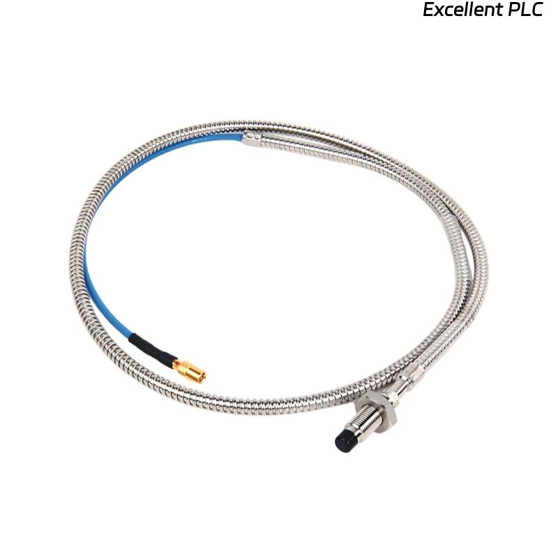
Recently, I encountered a Bently Nevada 129716-XXX-037-15-05 proximity probe module where the probe cable had broken near the connector, causing loss of signal. This situation is common in high-vibration turbine environments, and careful repair is essential to maintain accurate shaft monitoring and vibration protection. Here’s a step-by-step approach I used in the field.
Step 1: Safety and Initial Assessment
-
Power down the turbine and 3500 monitoring system before handling the module or probe.
-
Confirm part number: 129716-XXX-037-15-05.
-
Gather tools: multimeter, wire stripper, soldering kit or crimp connectors, heat shrink tubing, ESD wrist strap, and cleaning cloth.
-
Inspect the broken cable for location of the cut and any exposed shielding.
Field tip: Even a small short or misconnection can damage the module when powered up.
Step 2: Cable Preparation
-
Identify the exact location of the break.
-
Strip back the insulation on both ends of the broken wire (~8–10 mm).
-
Carefully untwist the shield braid if present and ensure continuity.
-
Check that conductors are clean, untarnished, and intact.
Field insight: Protecting the shield is crucial to maintain low-noise signal transmission.
Step 3: Reconnecting the Wires
There are two main methods: soldering or crimping.
Option A: Soldering
-
Twist the conductor ends together.
-
Apply solder carefully, avoiding excess heat that could damage insulation.
-
Slide heat shrink tubing over the joint and shrink to protect from moisture.
-
Ensure the shield is reconnected to maintain grounding.
Option B: Crimp Connector
-
Use a miniature crimp butt connector compatible with wire gauge.
-
Insert wire ends and crimp securely.
-
Cover the joint with heat shrink tubing.
-
Reconnect the shield braid properly to maintain continuity.
Field tip: Avoid sharp bends near the repair; secure the cable to reduce vibration stress.
Step 4: Verify Continuity
-
Use a multimeter to check:
-
Continuity of the signal wire from probe tip to module input.
-
Continuity of the shield to the module ground.
-
-
Ensure no shorts between conductors or to the shield.
Field insight: A visual repair may look fine, but electrical testing is critical before powering up.
Step 5: Reconnect to Module and Rack
-
Reinsert the repaired probe connector into the module input.
-
Ensure a firm, fully seated connection.
-
Check all screws and locking mechanisms.
Step 6: Power-Up and Functional Test
-
Power up the 3500 system.
-
Observe LED indicators for normal operation.
-
Check the software readings for the repaired channel.
-
Gently move the probe target or shaft to verify smooth signal response.
Field tip: If readings are erratic, double-check wire polarity, shield continuity, and module seating.
Step 7: Preventive Measures
-
Use cable support clamps to prevent future stress near connectors.
-
Document the repair location and serial number for maintenance history.
-
Periodically inspect for wear or insulation damage in high-vibration areas.
Key Takeaways
-
A broken proximity probe wire can be repaired in the field if done carefully with proper tools and shielding.
-
Testing for continuity and ensuring correct grounding is essential before powering the module.
-
Preventive cable routing and strain relief reduce recurrence of wire breaks.
“A precision proximity probe depends on every conductor and shield — a careful repair keeps your monitoring system reliable.”