

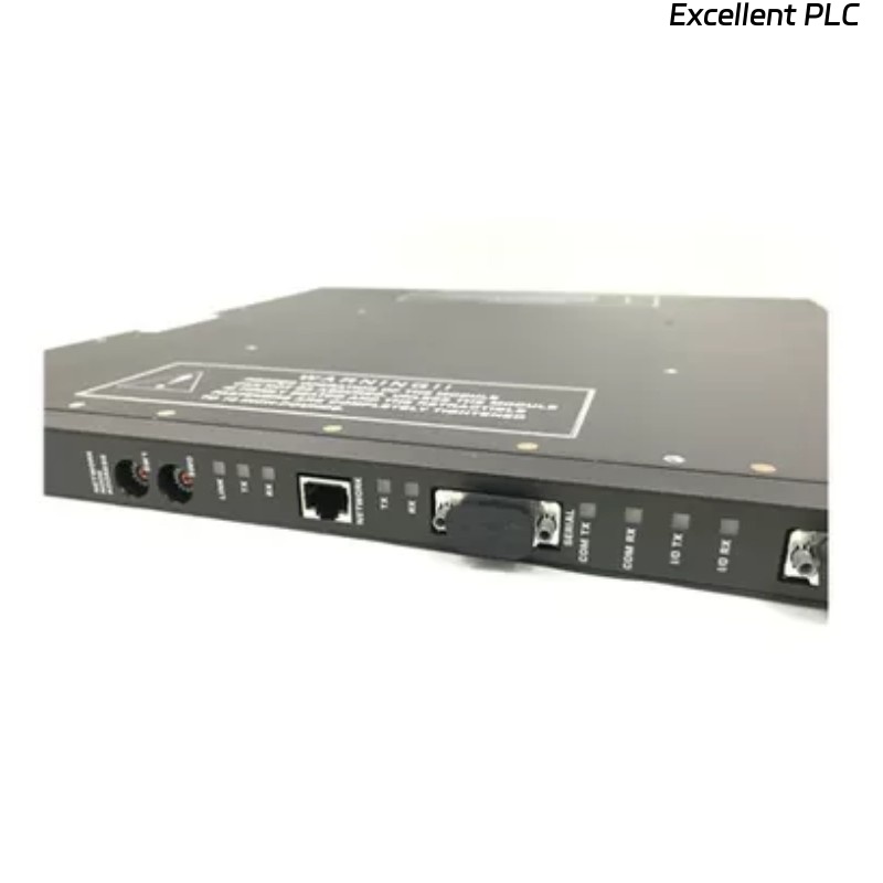
The Triconex 4000188-330 is an interface module used in TMR (Triple Modular Redundant) systems to provide communication between the main controller and peripheral devices. When the module shows no response after installation, it can disrupt system operation. The following guide outlines systematic troubleshooting and repair steps used by experienced field engineers.
1. Safety Precautions
-
Power Off the Chassis – Ensure the rack is completely de-energized before handling the module.
-
ESD Protection – Wear anti-static wrist straps and work on an ESD-safe mat.
-
Documentation Check – Keep wiring diagrams, module datasheets, and system topology handy.
2. Visual Inspection
-
Check Module Condition – Look for physical damage, burnt components, or broken connectors.
-
Inspect Rack Slot – Ensure the backplane connector is clean and free from dust, corrosion, or bent pins.
-
LED Indicators – Verify if any LEDs on the module light up. No LEDs may indicate a power issue or poor connection.
Tip: Even minor connector contamination can prevent module initialization.
3. Power Verification
-
Measure Supply Voltage – Confirm that the rack provides the correct voltage to the module (commonly 5 V and 24 V).
-
Check for Ripple and Noise – Use an oscilloscope to detect voltage irregularities that may prevent module startup.
-
Test Connector Contact – Ensure the module is fully seated in the backplane; loose connections often cause “no response” symptoms.
4. Backplane and Chassis Checks
-
Swap Slots – Insert the module into a different, verified-good slot to rule out backplane issues.
-
Inspect Rack Power Distribution – Check if neighboring modules receive power correctly; if not, the fault may be in the chassis or power supply.
-
Redundant Path Verification – For TMR systems, ensure redundant connections are not preventing initialization due to mismatch or misalignment.
5. Module-Level Troubleshooting
-
Compare with a Known-Good Module – Place a working 4000188-330 module in the same slot to determine if the issue is module-specific.
-
Component-Level Check – Examine regulators, driver ICs, and capacitors. Replace any obviously degraded components.
-
Firmware/Configuration – Verify the module firmware is compatible with the system. In rare cases, reloading or updating firmware may restore function.
6. Communication Interface Checks
-
Check Network Cabling – For Ethernet or Triconex high-speed links, verify cable continuity, connectors, and shielding.
-
Protocol Verification – Use system diagnostics to confirm if the module is recognized on the network.
-
Check Redundancy Alignment – Ensure the interface module is configured correctly within the redundant control network.
7. Post-Repair Validation
-
Bench Test – Connect the repaired module in a test rack to verify LED and communication responses.
-
Monitor System Recognition – Use Triconex diagnostic software to ensure the module is correctly detected and functioning.
-
Burn-In Test – Run the module under load for several hours to ensure stable operation before reinstallation in the production system.
Common Causes of “No Response”
-
Improper seating in the backplane connector
-
Contaminated or oxidized connectors
-
Power supply issues (incorrect voltage or ripple)
-
Failed driver ICs or power regulators
-
Mismatched firmware or misconfigured redundancy
-
Faulty cabling in network interfaces
Key Takeaways
-
Always start troubleshooting from power and connectors, then move to module-level electronics.
-
Use a known-good module as a comparison to isolate faults quickly.
-
Inspect chassis and backplane for damage before assuming module failure.
-
Document all repairs and test results to maintain system safety integrity.