

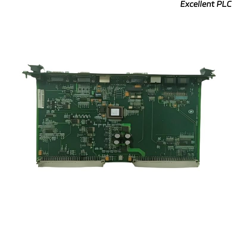
The ABB 07 AA 65 R1 (GJV3074369R1) is a high-precision analog output module, frequently used in closed-loop control where signal accuracy matters more than speed.
Because of that, even small installation or wiring mistakes tend to surface later as “mysterious” control problems.
This article focuses strictly on how it fails, how to judge it, and how to install it correctly.
Typical Reasons It Gets Sent for Repair
In real maintenance records, this module is usually removed for one of these reasons:
-
Output value unstable or drifting
-
Output correct with meter, wrong at actuator
-
Channel works after power cycle, then degrades
-
No alarm, but process cannot be tuned
Most of these are electrical stress problems, not logic issues.
First-Level On-Site Troubleshooting (Before Removal)
Before pulling the module, do these checks:
-
Measure output current directly at the terminal
-
Disconnect the field load and re-measure
-
Check load resistance against ABB specifications
-
Inspect shield grounding (single-point only)
If the output stabilizes with the load disconnected, the module is already partially damaged.
Common Internal Damage Found During Repair
When inspected on the bench, failed 07 AA 65 R1 modules often show:
-
Degraded output driver components
-
Shifted reference voltage levels
-
Heat discoloration near the output stage
-
Terminal interface fatigue
These faults are cumulative and usually irreversible.
Can It Be Repaired?
From a practical standpoint:
-
Output driver damage → not recommended to repair
-
Reference drift → not repairable reliably
-
Terminal block damage → sometimes repairable
-
Safety or critical control loop → replace only
Component-level repair rarely restores long-term stability.
Correct Installation Procedure (Step-by-Step)
Installation quality directly determines service life.
Recommended procedure:
-
Isolate rack power completely
-
Discharge all field wiring (especially inductive loads)
-
Verify module type and channel assignment
-
Insert module vertically without lateral force
-
Secure terminals evenly
-
Reconnect field wiring only after visual inspection
Never hot-plug this module under load.
Wiring Rules That Prevent Repeat Failures
Field experience strongly supports these practices:
-
Do not share return paths between AO channels
-
Keep AO cables physically separate from DO wiring
-
Avoid routing near VFD or high-frequency sources
-
Use proper suppression on inductive actuators
Most repeat failures are wiring-related, not module-related.
Basic Output Verification After Installation
After power-up, perform a functional test:
Then measure:
-
Output current stability
-
Actuator response consistency
-
Absence of oscillation or delay
Testing only 0% and 100% is not sufficient—mid-scale behavior matters most.
Final Maintenance Advice
If a 07 AA 65 R1 has already shown drift once, reinstalling it in another loop is risky.
Analog output modules remember their stress history.
In critical loops, replacement is cheaper than repeated troubleshooting.