

Introduction
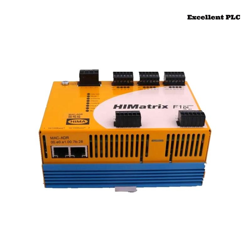
The Black Horse F1 DI 16 01 Remote I/O Module is widely used in distributed control systems (DCS) and industrial automation architectures to acquire digital input signals from field devices such as limit switches, proximity sensors, and safety contacts. As a remote I/O component, its reliability directly affects system visibility and control accuracy.
This article addresses one representative failure mode among many possible faults: partial digital input channel failure, where some input channels stop responding or exhibit unstable state changes while the module remains online. The guide provides practical diagnostic instructions, maintenance procedures, and engineering-level troubleshooting steps for field technicians and automation engineers.
Fault Scenario Overview
Fault Mode:
Several input channels (e.g., DI05–DI08) on the F1 DI 16 01 module fail to detect valid field signals, while other channels continue to operate normally.
Typical Symptoms:
-
Field devices are physically actuated, but corresponding input bits do not change
-
Intermittent “ON/OFF” flickering on specific channels
-
PLC/DCS diagnostics indicate “I/O mismatch” or “channel no response”
-
Temporary recovery after power cycling the remote I/O station
Step-by-Step Diagnostic Procedure
1. Logical Input Status Verification
From the control system or engineering workstation, verify the real-time state of the digital inputs:
If only specific channels show abnormal behavior, the fault is likely localized to the channel input circuitry rather than the entire module power supply or communication interface.
2. Field Signal Validation
Before suspecting the module, validate the field wiring and sensors:
If valid voltage is present at the terminal but the input state does not update, the issue is likely internal to the module.
3. Module Self-Diagnostic Review
Check remote I/O node diagnostics:
This diagnostic pattern often indicates partial failure of the input conditioning or opto-isolation circuitry.
Root Cause Analysis
Partial channel failure in digital input modules is commonly associated with:
-
Degraded optocouplers on specific channels due to long-term high-duty switching
-
Surge or transient overvoltage events damaging individual input circuits
-
Terminal block oxidation causing intermittent signal conduction
-
PCB contamination (oil mist, dust, or moisture) affecting signal conditioning components
Unlike total module failure, these faults progress gradually and are often overlooked until multiple channels become unusable.
Repair and Maintenance Actions
Channel Isolation and Reassignment (Temporary Mitigation)
As a short-term operational workaround:
Physical Inspection and Restoration
If channel faults persist after cleaning and reseating, the internal input circuitry is likely damaged.
Functional Verification After Repair
If any channels remain unresponsive, full module replacement is recommended for long-term reliability, especially in safety-related or production-critical loops.
Preventive Maintenance Best Practices
-
Implement surge protection on field wiring connected to digital inputs
-
Use shielded cables in high-interference environments
-
Perform annual inspection of terminal blocks and connectors
-
Trend I/O channel fault statistics to detect early degradation
-
Keep spare F1 DI 16 01 modules in inventory for critical remote I/O stations
Conclusion
Partial digital input channel failure in the Black Horse F1 DI 16 01 Remote I/O Module is a typical aging-related fault that can significantly impact control system reliability. By applying structured diagnostics, validating field signals, and following standardized maintenance procedures, engineers can quickly isolate the fault and restore stable operation. Proactive preventive maintenance and timely module replacement remain the most effective strategies to ensure long-term reliability in distributed I/O architectures.