

Incident Overview
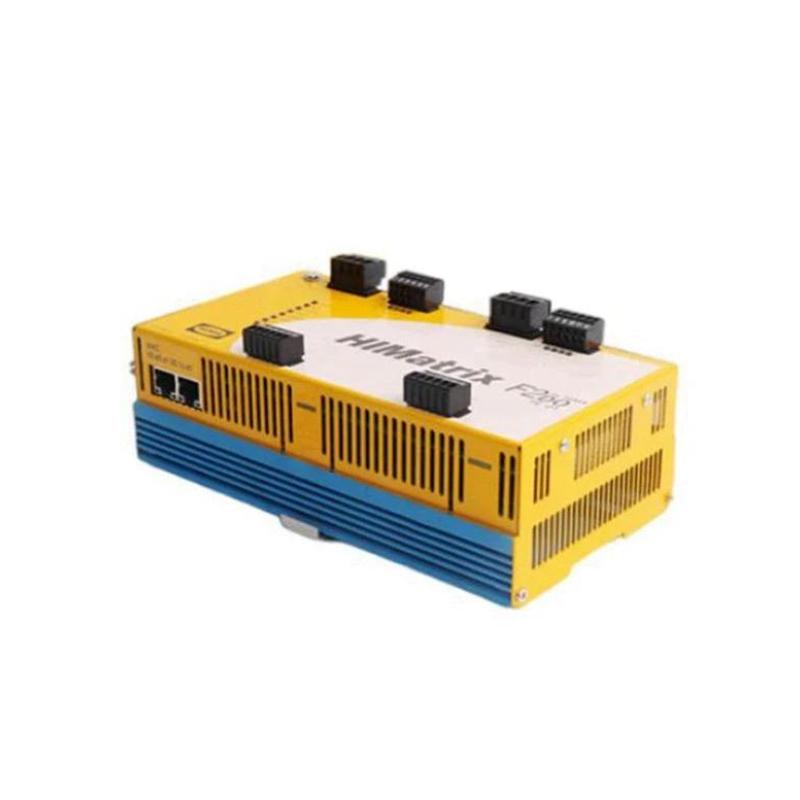
In an industrial HIMatrix safety cabinet, four adjacent output channels on the Black Horse F2 DO 16 01 Remote I/O Module stopped working simultaneously.
Observed symptoms:
-
Channels DO5–DO8 inactive
-
Controller showed outputs ON
-
No voltage present at output terminals
-
Other channels (DO1–DO4, DO9–DO16) functioning normally
-
No communication fault
This pattern strongly suggested a grouped hardware issue rather than individual transistor failure.
Internal Output Group Architecture
Many 16-channel digital output modules divide outputs into groups sharing:
-
Common supply rail
-
Shared protection circuit
-
Group fuse or electronic protection
-
Common return reference
When multiple adjacent outputs fail together, the group supply must be investigated.
Step 1 – Verify Controller Logic
1. Monitor output commands in controller.
2. Confirm no program inhibit active.
3. Check safety interlock status.
All commands verified active.
Step 2 – Measure Group Supply Voltage
1. Identify supply terminal for affected group.
2. Measure voltage between supply and return.
3. Compare with functioning group supply.
Result: 0V measured on affected group supply terminal.
Healthy groups measured 24VDC.
Root Cause – External Supply Fuse Blown
The F2 DO 16 01 module uses separate external supply inputs per output group.
Investigation found:
-
External 24V supply fuse feeding DO5–DO8 was blown
-
Cause traced to temporary short during maintenance
-
Module itself was not damaged
This is a classic grouped failure signature.
Step 3 – Confirm No Internal Damage
1. Replace external fuse.
2. Disconnect field loads.
3. Re-energize supply.
4. Measure output voltage without load.
Voltage restored to 24VDC.
Outputs switched normally after load reconnection.
Why This Happens Frequently
Grouped failures often result from:
-
External short circuits
-
Incorrect load wiring
-
Excessive inrush current
-
Maintenance errors
-
Underrated supply protection devices
The module is often blamed, but supply infrastructure is the real cause.
Corrective Action Plan
– Replace blown fuse with correctly rated type.
– Inspect downstream wiring.
– Verify load current specification.
– Implement surge suppression where needed.
Engineering Best Practices
-
Label output group supply terminals clearly.
-
Use properly rated fast/slow-blow fuses depending on load type.
-
Separate high-inrush loads across groups.
-
Always test group voltage before replacing modules.
Many modules are unnecessarily replaced due to overlooked supply faults.
Conclusion
When multiple adjacent outputs fail simultaneously on the Black Horse F2 DO 16 01 Remote I/O Module, the most common cause is group-level supply interruption rather than internal electronic failure. Structured voltage measurement at group supply terminals quickly confirms the root cause and prevents unnecessary module replacement in HIMatrix systems.