

Chapter 5: Timer Module Diagnostics
5.1 Symptom Description
-
Timer output triggers earlier or later than configured
-
No module fault LED illuminated
-
PLC reports sequence anomaly
-
Field wiring verified correct
Example: Configured delay 2s → measured delay 3.8s
5.2 Required Tools
-
Engineering programming station
-
Digital multimeter (DC 24V, mV precision)
-
Oscilloscope (≥10 MHz bandwidth)
-
Torque screwdriver for terminal check
-
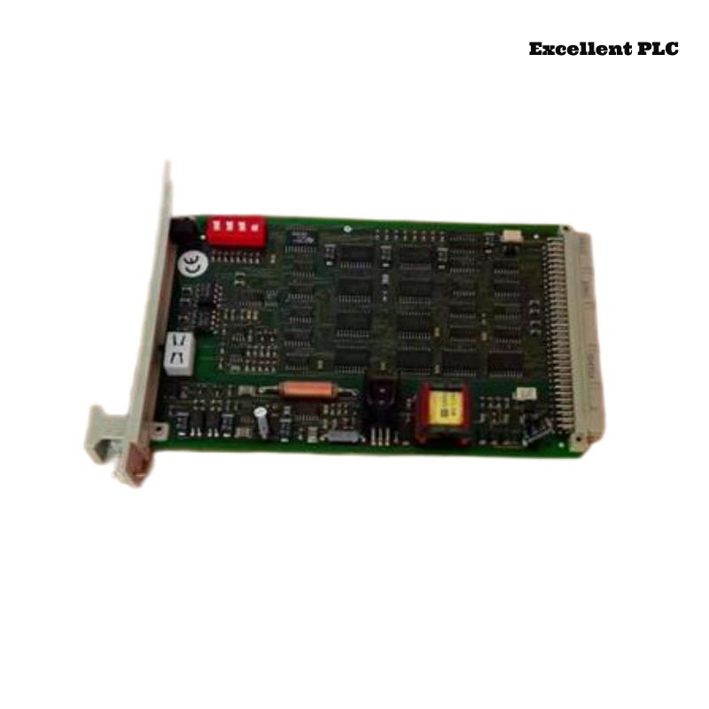
Spare F2103a module (for replacement verification)
5.3 Step-by-Step Diagnostic Procedure
Step 1: Configuration Verification
2. Read timer preset value.
3. Compare with project archive.
4. Confirm RUN mode.
-
Expected: Preset value matches design specification
-
Observed deviation indicates either corrupted memory or internal drift
Step 2: Output Verification
2. Trigger timer input.
3. Measure output terminal voltage with DMM.
4. Record activation timing.
-
If output triggers correctly: external load wiring issue suspected
-
If output triggers incorrectly: internal timing logic or supply issue suspected
Step 3: Power Supply Assessment
2. Observe for dips during full cabinet load.
3. Verify ripple < 150 mV peak-to-peak.
-
Supply dips or spikes > ±10% can corrupt counter logic
Step 4: Oscilloscope Timing Verification
2. Probe output terminal (CH2).
3. Capture at 1 kHz repetition.
4. Measure actual delay per cycle.
5. Repeat for 20 cycles.
-
Calculate mean delay and standard deviation
-
Compare with configured value
5.4 Fault Identification
-
Internal oscillator drift → delays longer than expected
-
Power sag or ripple → counter register resets, causing early trigger
-
Memory corruption → configuration CRC mismatch
5.5 Corrective Action
-
Replace F2103a module if timing drift > ±5% of specification
-
Verify PSU stability
-
Re-download timer configuration
-
Perform 50-cycle validation test
– Delay within ±2% of nominal
– Output LED functions correctly
– Safety PLC sequence restored
5.6 Preventive Maintenance
-
Annual timing verification under full load
-
Monitor supply voltage dips during operation
-
Maintain spare timer modules for critical circuits
-
Avoid environmental extremes (temperature > 60°C)
5.7 Notes
-
Timer drift failures are subtle; they appear as functional but unsafe behavior
-
Always measure real-world timing with oscilloscope before assuming module healthy
Conclusion:
Following this structured manual procedure ensures correct diagnosis and repair of Black Horse F2103a Timer Module timing faults in Planar F safety applications.