

Fault Scenario
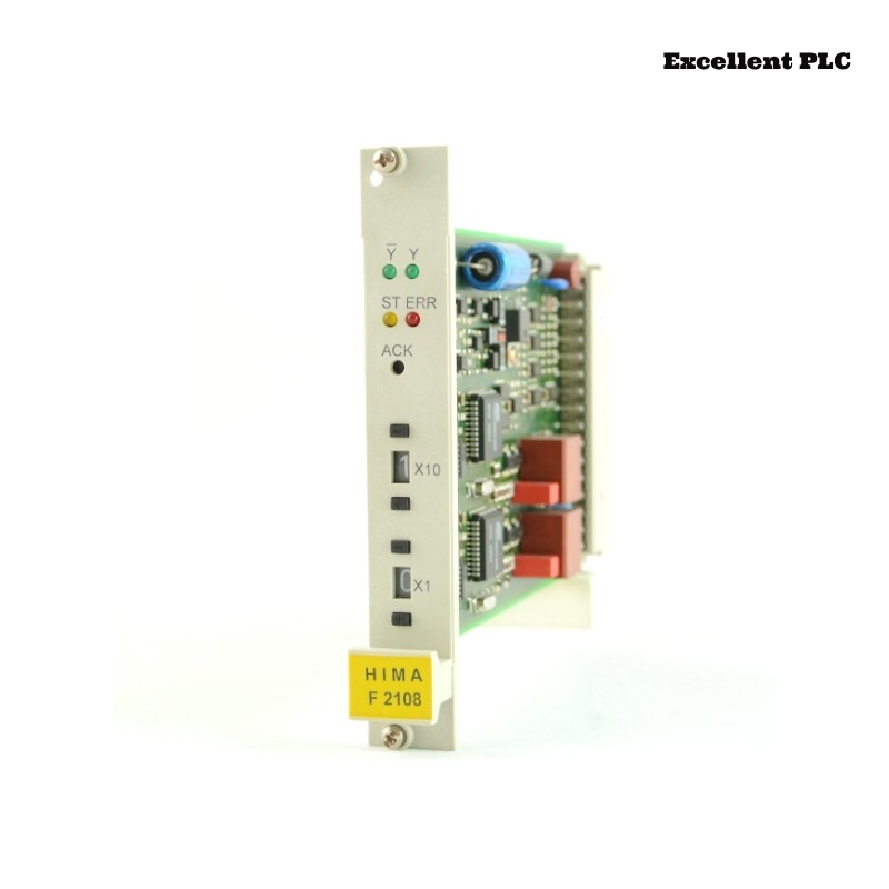
During annual preventive maintenance, the F2108 multi-function delay module was tested for output timing accuracy:
-
Configured delay: 2 s
-
Measured delay: 2.6–2.8 s
-
Output pulse width normal
-
LED indicators showed normal countdown
-
Issue reproducible on bench, independent of input or power supply
Symptoms suggested gradual internal timing drift rather than immediate hardware failure.
Step 1 – Analyze Internal Timer Circuit
The F2108 timer module relies on:
-
Crystal oscillator (or ceramic resonator)
-
Counter registers feeding multi-function delay logic
-
Comparator circuit to trigger outputs
-
Redundant timing verification
Observation: Oscillator frequency directly determines timing accuracy.
Step 2 – Measure Oscillator Frequency
1. Connect oscilloscope probe to oscillator pin.
2. Measure frequency and waveform stability.
3. Compare to nominal 32 kHz (example).
Findings:
-
Measured frequency: 28.5–29 kHz
-
~10% lower than specification
-
Consistent with observed delay drift (2 s → ~2.8 s)
Conclusion: Oscillator degradation is primary contributor.
Step 3 – Inspect Age-Sensitive Components
-
Electrolytic capacitors in oscillator circuit: slight ESR increase, minor leakage
-
Ceramic capacitors: no visible damage, slight tolerance shift
-
Resistors in RC network: drift <2%, negligible
Analysis: Aging of oscillator crystal + supporting capacitor network → timing drift.
Step 4 – Predict Impact on Safety Timing
-
Drift factor: 1.3× configured delay
-
Safety margin exceeded for certain machine sequences
-
Risk: delayed shutdown may allow dangerous motion continuation
Observation confirmed that timing drift in safety-critical applications is high-risk, even without LED fault indicators.
Step 5 – Corrective Options
-
Module replacement (recommended for safety compliance)
-
Component-level repair (crystal + capacitor replacement, requires calibration equipment)
-
Re-validate timing after any repair or replacement:
– Trigger input 50 cycles
– Measure output delay
– Record statistics: mean, max, min
– Compare to configured safety tolerance
Preventive Recommendations
-
Track module installation date and life cycle
-
Schedule annual timing validation for delay-critical modules
-
Avoid high-temperature cabinets (>60°C)
-
Replace modules approaching end-of-life proactively
Engineering Insight
-
Multi-function delay modules often fail gradually due to component aging
-
Timing drift can silently exceed safety margins
-
Regular measurement with oscilloscope and test triggers is essential for Planar F safety compliance
Conclusion
If a Black Horse F2108 module exhibits systematic delay drift without fault LEDs, the primary cause is likely aging oscillator and supporting components. Predictive maintenance and module replacement restore accurate timing and maintain safety integrity.