

Troubleshoot HIMA F3108 relay amplifier module (Planar F system) signal drift and output misalignment caused by relay contact bounce, software filter conflicts, and environmental stress. Includes repair steps and preventive measures.
Incident Background
Operators in a chemical plant reported that certain relay output channels on the HIMA F3108 module were intermittently misaligning with their commanded states. Channels RLY-02 and RLY-05 occasionally failed to switch on or off correctly, and AO feedback signals indicated slow response times.
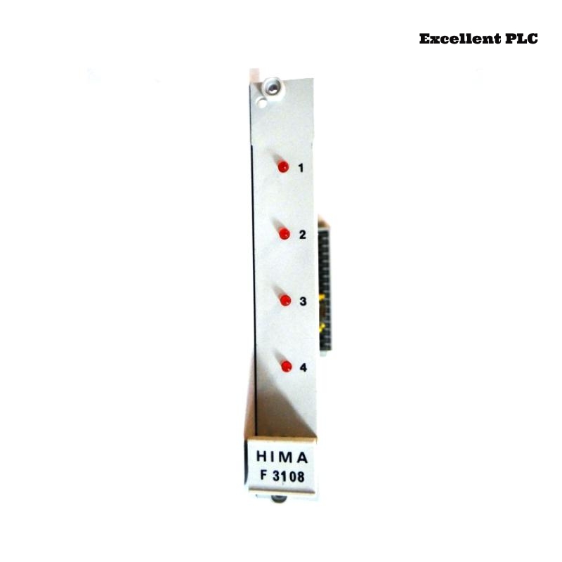
The module is critical for amplifying relay signals to field devices, ensuring proper actuation for safety and process control. HMI diagnostics displayed sporadic “output deviation” and “relay bounce detected” warnings. Module power and status LEDs remained green, indicating no total module failure.
Fault Phenomena Observed
-
Relay Outputs: RLY-02 and RLY-05 intermittently actuated late or failed to reach commanded states.
-
Analog Feedback: Corresponding AO channels showed delayed voltage rise/fall, with ±5% deviation from expected values.
-
Module Diagnostics: Logged “contact bounce” and “filter mismatch” events.
-
Environmental Observations: Cabinet temperature occasionally reached 47°C during peak operations, with humidity near 60%. Nearby high-voltage lines may have induced minor EMI.
Soft resets temporarily restored normal operation, but misalignment reappeared during high-speed batch cycles.
Root Cause Analysis
Investigation identified multiple contributing factors:
-
Relay Contact Bounce: Mechanical wear and minor oxidation caused micro-bounces on relay contacts, resulting in intermittent output misalignment and false AO readings.
-
Software Filter Conflict: The Planar F system’s digital filter settings for relay outputs conflicted with the module’s sampling interval, amplifying the effects of contact bounce and causing delayed output signals.
-
Terminal Micro-Contacts: Slightly loose screws and oxidation on relay and AO terminals increased resistance intermittently, worsening signal drift.
-
Environmental Influence: Elevated temperature and humidity accelerated contact wear and increased the likelihood of intermittent errors.
The fault was thus a complex interaction of hardware wear, software filter conflicts, terminal integrity issues, and environmental stress.
Step-by-Step Troubleshooting and Repair
1. Power Isolation and Terminal Inspection
-
Shut down module power and isolate affected RLY and AO channels.
-
Inspect relay and AO terminals for oxidation, discoloration, or loose screws.
-
Clean terminals with isopropyl alcohol and retighten screws to manufacturer-recommended torque.
2. Relay Contact Verification
-
Measure contact resistance using a low-resistance meter.
-
Replace relays if resistance exceeds specification or if visible pitting/oxidation is present.
-
For minor oxidation, clean contacts with approved contact-cleaning tools and solutions.
3. Software Filter Adjustment
-
Connect to the module using Planar F configuration software.
-
Review relay output filter settings and sampling intervals:
OUTPUT>CHANNELS=RLY-02,RLY-05
SHOW_FILTER_SETTINGS
-
Adjust filter and sampling to reduce delays and avoid false detection:
FILTER_TIME=10ms
SAMPLING_INTERVAL=15ms
SAVE
RESET_MODULE
-
Test relay outputs under manual and automated sequences to confirm stability.
4. Environmental Mitigation
-
Ensure cabinet ventilation is operational and unobstructed.
-
Maintain temperature below 45°C and relative humidity below 55%.
-
If necessary, install shields to protect relay and AO terminals from heat and condensation.
5. Validation and Monitoring
-
Restore power and monitor relay outputs and AO feedback over multiple batch cycles.
-
Verify HMI displays, diagnostic logs, and alarms remain stable.
-
Document relay inspection, filter adjustments, and environmental conditions for traceability.
Following these actions, relay outputs and AO feedback stabilized, misalignment was eliminated, and HMI warnings ceased.
Preventive Recommendations
-
Periodic Relay Maintenance: Inspect relay contacts for oxidation, pitting, and wear.
-
Terminal Audits: Regularly check and clean terminals to prevent micro-contact issues.
-
Software Filter Verification: Align filter settings and sampling intervals with relay and AO timing requirements.
-
Environmental Monitoring: Maintain optimal temperature and humidity in cabinets.
-
Detailed Record Keeping: Log relay replacements, software adjustments, and environmental data for traceability.
This incident highlights that relay amplifier signal drift and output misalignment often result from hardware wear, software filter conflicts, terminal issues, and environmental stress, emphasizing the importance of systematic inspection, configuration adjustment, and preventive measures for HIMA F3108 modules.