

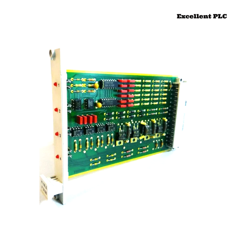
Troubleshoot output oscillation and signal drift in HIMA F3108 relay amplifier modules (Planar F system) caused by input interference, relay contact aging, and firmware logic anomalies. Includes step-by-step repair and preventive measures.
Incident Background
Operators at a chemical processing facility reported that certain relay outputs on the HIMA F3108 module were oscillating unexpectedly during batch operation. Channels RLY-01, RLY-04, and RLY-07 occasionally cycled rapidly between on and off states, causing erratic actuator behavior and minor process fluctuations.
The HMI displayed “output instability” and “signal drift detected” warnings. Power and status LEDs on the module remained green, indicating no complete module failure. Initial soft resets temporarily reduced oscillation, but the issue recurred during high-speed sequential operations.
Fault Phenomena Observed
-
Relay Outputs: RLY-01 and RLY-07 experienced rapid intermittent toggling, sometimes 2–3 cycles per second.
-
Analog Feedback: Corresponding AO signals drifted ±5% from expected values, affecting downstream safety loops.
-
Module Diagnostics: Logged “input interference” and “firmware logic anomaly” events.
-
Environmental Observations: Cabinet temperature reached ~50°C under peak load, and humidity was ~60%. Nearby high-current cables may have introduced minor electromagnetic interference (EMI).
Root Cause Analysis
Investigation revealed multiple contributing factors:
-
Input Interference: Long analog input wiring near high-current power lines introduced transient noise, causing the module to misinterpret signals and trigger output oscillation.
-
Relay Contact Wear: Mechanical aging and minor oxidation on relay contacts amplified signal instability, contributing to intermittent toggling.
-
Firmware Logic Anomalies: Certain Planar F firmware versions contained timing misalignment between input sampling and output actuation, causing oscillation under rapid input changes.
-
Terminal Micro-Contacts: Loose or oxidized screws at RLY and AO terminals increased resistance, worsening signal drift and oscillation.
-
Environmental Stress: Elevated temperature and humidity accelerated contact degradation and affected signal integrity.
The fault resulted from a combination of input interference, relay contact wear, firmware logic timing, terminal issues, and environmental factors.
Step-by-Step Troubleshooting and Repair
1. Power Isolation and Terminal Inspection
-
Shut down module power and isolate affected relay channels.
-
Inspect RLY and AO terminals for oxidation, discoloration, or loose screws.
-
Clean terminals using isopropyl alcohol and retighten according to manufacturer specifications.
2. Relay Verification and Replacement
-
Measure contact resistance using a low-resistance meter.
-
Replace relays if resistance exceeds specifications or if visible oxidation/pitting is present.
-
Minor oxidation can be removed carefully with approved cleaning solutions.
3. Firmware Review and Update
-
Connect to the module using Planar F configuration software.
-
Check firmware version and verify compatibility with the system:
SHOW_FIRMWARE_VERSION
-
Update firmware if anomalies are known in the current version:
-
Confirm that output actuation timing aligns with input sampling.
4. Software Filter and Input Signal Adjustment
-
Check input signal filter settings to reduce transient noise influence:
SHOW_FILTER_SETTINGS
-
Adjust filter timing to smooth input and prevent false oscillation:
FILTER_TIME=15ms
SAVE
RESET_MODULE
5. Environmental Mitigation
-
Ensure cabinet ventilation is functioning properly.
-
Maintain temperature below 45°C and relative humidity below 55%.
-
Reroute high-current cables away from sensitive analog inputs to reduce EMI.
6. Validation and Monitoring
-
Restore power and monitor relay outputs and AO feedback over multiple batch cycles.
-
Verify HMI warnings, module diagnostics, and actual relay behavior for stability.
-
Document all inspections, relay replacements, firmware updates, and environmental adjustments for future reference.
After these steps, output oscillation ceased, AO signals stabilized, and process control returned to normal.
Preventive Recommendations
-
Relay Maintenance: Periodically inspect and replace worn or oxidized relay contacts.
-
Terminal Audits: Regularly clean and tighten terminals to avoid micro-contact resistance issues.
-
Firmware Management: Keep module firmware up-to-date to avoid known logic anomalies.
-
Input Signal Management: Filter analog inputs to reduce noise and prevent oscillation.
-
Environmental Control: Maintain optimal cabinet temperature and humidity, and avoid EMI exposure from nearby power lines.
-
Record-Keeping: Track relay inspections, firmware updates, and environmental readings for traceability.
This incident highlights that relay amplifier output oscillation and signal drift often result from hardware aging, input interference, firmware timing anomalies, terminal integrity, and environmental stress, emphasizing the importance of systematic inspection, software adjustment, and preventive maintenance for HIMA F3108 modules.