

Table of Contents
- Bently Nevada 130539-99 Cable Installation Overview
- Function of 130539-99 in Monitoring Systems
- Installation Planning and Layout Strategy
- Cable Routing and EMI Control
- Connection and Termination Best Practices
- System Setup and Configuration
- Commissioning and Signal Validation
- Field Installation Case
- Installation FAQ
- Final Engineering Summary
Bently Nevada 130539-99 Cable Installation Overview
Bently Nevada 130539-99 interconnect cable installation directly affects vibration monitoring accuracy. In real projects, signal instability is often caused by routing and grounding issues rather than sensor or module faults.
This Installation Guide focuses on practical setup, wiring discipline, and commissioning validation for stable long-distance signal transmission.
Function of 130539-99 in Monitoring Systems
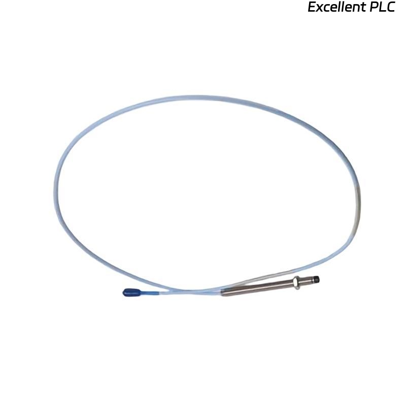
The 130539-99 is a 3-conductor shielded interconnect cable used to connect proximity probes or accelerometers to Bently Nevada monitoring systems such as 3500 racks. :contentReference[oaicite:0]{index=0}
- Supports vibration and displacement signal transmission
- Maintains signal integrity over long distances (~30m)
- Reduces EMI through shielded twisted-pair design
- Compatible with 3300 / 3500 monitoring systems
Installation Planning and Layout Strategy
- Define routing path before installation (avoid re-routing later)
- Maintain minimum 300 mm separation from power cables
- Ensure cable length (99 ft / ~30 m) fits system layout without tension :contentReference[oaicite:1]{index=1}
- Plan grounding scheme (single-point grounding only)
Cable Routing and EMI Control
- Avoid parallel routing with VFD output cables
- Use dedicated signal cable trays when possible
- Protect cable from mechanical damage and vibration
- Maintain bend radius ≥5× cable diameter :contentReference[oaicite:2]{index=2}
  // EMI Prevention Logic
  IF Noise_Level_High AND Cable_Close_To_Power THEN
      Re-route_Cable();
  END_IF;
Connection and Termination Best Practices
- Ensure tight connection at probe and monitor terminals
- Verify correct polarity of signal conductors
- Ground shielding at monitor side only
- Inspect connectors for oxidation or loose contact
System Setup and Configuration
- Configure channel type (proximity / vibration) in 3500 system
- Set scaling factor according to sensor type
- Verify alarm thresholds and system configuration
- Check signal mapping from field to PLC/monitor
Commissioning and Signal Validation
- Measure baseline signal at idle condition
- Verify stable waveform (no spikes or distortion)
- Compare readings with portable analyzer
- Run machine under load and monitor consistency
Field Installation Case
In a refinery compressor system, a 130539-99 cable was installed alongside a 480V motor feeder. During commissioning:
- Signal spikes reached 16 mm/s peak
- Noise synchronized with motor switching events
Engineers initially suspected sensor failure. After rerouting the cable and correcting shield grounding:
- Noise reduced by ~70%
- Signal stabilized at 4.1 mm/s RMS
Installation FAQ
Why must shielding be grounded at only one end?
To prevent ground loops, which introduce noise into vibration signals.
Can I install this cable near power cables?
It is strongly discouraged. Maintain separation to avoid EMI interference.
What is the typical length of 130539-99?
The “-99” option typically indicates a cable length of approximately 99 feet (~30 meters).
Final Engineering Summary
The Bently Nevada 130539-99 Installation Guide emphasizes routing discipline, shielding integrity, and correct system configuration. Reliable signal transmission depends more on installation quality than cable specification alone.