

Table of Contents
- Bently Nevada 130938-10-10-01-00 Troubleshooting Entry
- Symptom-Oriented Fault Diagnosis Approach
- Diagnostic Flow for Sensor Signal Abnormalities
- Hidden Causes of Vibration Probe Fault
- Real Case: False High Vibration Alarm
- Repair Actions and System Recovery
- FAQ
- Technical Summary
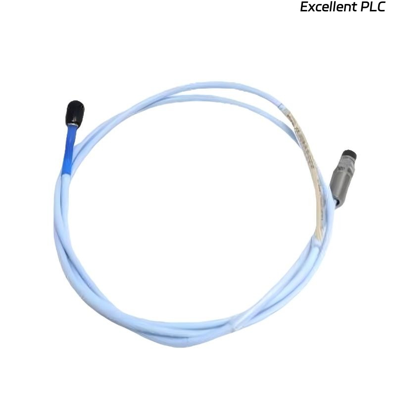
Bently Nevada 130938-10-10-01-00 Troubleshooting Entry
Bently Nevada 130938-10-10-01-00 vibration probe sensor troubleshooting often reveals that abnormal signals originate from installation or environmental interference rather than sensor failure.
This guide provides a fault diagnosis framework based on real signal behavior in industrial systems.
Symptom-Oriented Fault Diagnosis Approach
Instead of replacing components, engineers analyze symptoms:
- Sudden spike → possible grounding issue
- Gradual increase → contamination or thermal drift
- Signal drop to zero → power or cable fault
- Constant high reading → probe gap too small
This method aligns with real-world troubleshooting practices.
Diagnostic Flow for Sensor Signal Abnormalities
INPUT: abnormal vibration signal

IF signal fluctuates randomly:
    check EMI sources
    inspect shielding

IF signal increases over time:
    inspect probe surface
    check temperature effects

IF signal = 0:
    verify power supply
    test cable continuity

IF signal constant high:
    measure probe gap
    adjust mechanically
This logic helps isolate root causes efficiently.
Hidden Causes of Vibration Probe Fault
- Ground loop between sensor and PLC module
- Cable insulation degradation
- Probe tip contamination (oil film)
- Incorrect system configuration parameters
- Mechanical misalignment during installation
Real Case: False High Vibration Alarm
In a centrifugal compressor system, continuous high vibration alarms (>10 mm/s) were triggered.
Investigation:
- No abnormal mechanical vibration detected
- Sensor output voltage fluctuating
- Signal affected when nearby inverter started
Root Cause: Electromagnetic interference from inverter due to poor cable routing.
Result: After rerouting cable and improving grounding, vibration stabilized at 3.6 mm/s.
Repair Actions and System Recovery
- Re-route cables away from high-power equipment
- Re-establish proper grounding scheme
- Clean probe tip and recalibrate gap
- Replace damaged connectors if needed
Always perform commissioning checks after repair to confirm stability.
FAQ
Why does vibration increase when nearby equipment starts?
This is typically caused by electromagnetic interference affecting the sensor signal.
How to confirm if the probe itself is faulty?
Test output voltage independently and compare with calibration standards.
Is cable routing really that critical?
Yes, improper routing is one of the most common causes of false vibration readings.
Technical Summary
This Troubleshooting Guide demonstrates that most Bently Nevada 130938-10-10-01-00 vibration probe sensor faults are related to signal integrity issues rather than hardware damage. A structured diagnostic process combined with real signal analysis ensures efficient fault resolution and system reliability.