

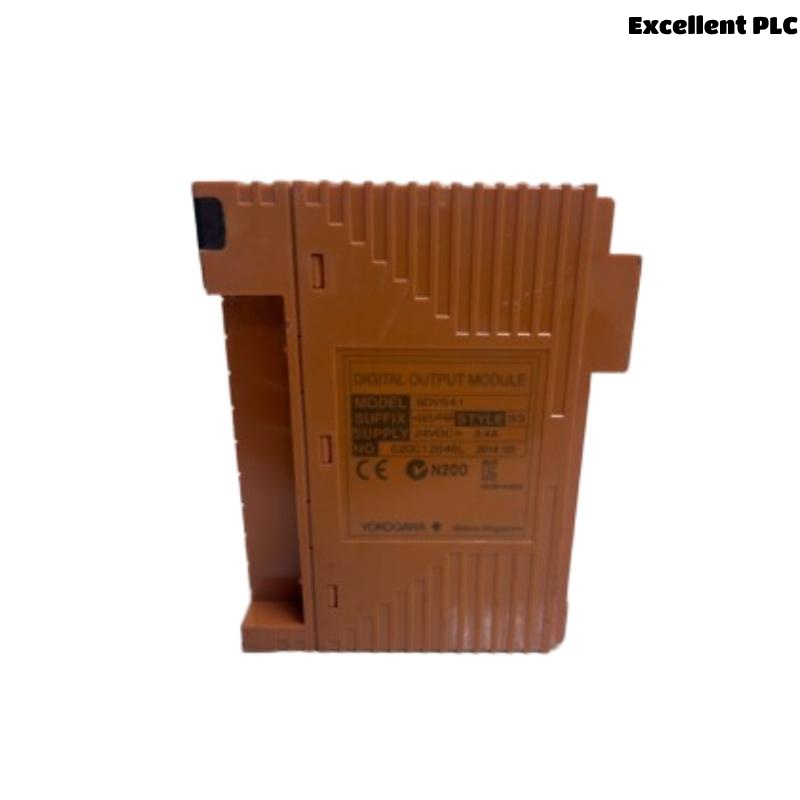
Yokogawa SDV541-S63/PRP output faults are usually caused by field wiring problems, overloaded output channels, external power supply abnormalities, or configuration errors rather than Digital Output Module hardware failure. Effective Troubleshooting requires a structured Fault Diagnosis process that evaluates electrical conditions before replacing the module. The SDV541-S63/PRP provides 16 isolated 24VDC outputs with a maximum load of 0.2A per channel and 3.2A total load capacity. :contentReference[oaicite:5]{index=5}
Contents
- SDV541-S63/PRP Fault Symptoms
- Operational Impact of Output Failures
- Typical Failure Patterns
- Common Causes of SDV541-S63/PRP Faults
- Fault Diagnosis Strategy
- Power Supply Troubleshooting
- Digital Output Channel Analysis
- Field Wiring Fault Diagnosis
- System Configuration Troubleshooting
- Electrical Measurements
- Diagnostic Workflow
- Repair Procedures
- Verification After Repair
- Preventive Maintenance
- Real Fault Diagnosis Case
- FAQ
SDV541-S63/PRP Fault Symptoms
- Output channel not switching
- Field device remains inactive
- Intermittent output signals
- Unexpected shutdown alarms
- Channel overload conditions
- Logic execution failures
Operational Impact of Output Failures
- Valve control loss
- Motor startup failure
- Safety action interruption
- Production downtime
- Alarm generation
Typical Failure Patterns
Field service teams frequently encounter the following situations:
- Single channel failure
- Multiple channel inactivity
- Output failure after maintenance
- Intermittent relay operation
- Power-related startup issues
Common Causes of SDV541-S63/PRP Faults
- 24VDC supply loss
- Incorrect wiring polarity
- Overloaded outputs
- Grounding problems
- Logic assignment errors
- Connector degradation
- Configuration mismatches
Fault Diagnosis Strategy
Experienced engineers investigate electrical conditions before replacing hardware.
- Review alarm history.
- Verify output commands.
- Measure voltage levels.
- Inspect field wiring.
- Validate System Configuration.
Power Supply Troubleshooting
| Observed Condition | Likely Cause |
|---|---|
| All outputs inactive | 24VDC supply failure |
| Random output loss | Voltage instability |
| Intermittent operation | Loose terminal connection |
| Channel overload alarm | Excessive load current |
Digital Output Channel Analysis
- Measure output voltage
- Verify switching status
- Monitor load current
- Check response time
- Review output diagnostics
Field Wiring Fault Diagnosis
- Inspect cable continuity
- Verify polarity
- Check terminal torque
- Inspect field devices
- Review cable routing
Most output failures originate from field wiring rather than module electronics.
System Configuration Troubleshooting
- Validate output mapping
- Review logic assignments
- Inspect controller database
- Verify channel allocation
- Check synchronization status
Electrical Measurements
| Parameter | Expected Value |
|---|---|
| Output Voltage | 24VDC |
| Voltage Drop | ≤1V |
| Channel Current | ≤0.2A |
| Total Current | ≤3.2A |
Diagnostic Workflow
CHECK ALARM HISTORY
VERIFY OUTPUT COMMAND
MEASURE 24VDC SUPPLY
INSPECT FIELD WIRING
VALIDATE CONFIGURATION
CONFIRM ROOT CAUSE
IMPLEMENT REPAIR
Repair Procedures
- Restore power supply
- Correct wiring polarity
- Replace damaged cables
- Repair field devices
- Update configuration database
Verification After Repair
- Output activation testing
- Current monitoring
- Logic validation
- Alarm clearance verification
- Integrated system testing
Preventive Maintenance
- Quarterly terminal inspections
- Routine load current review
- Annual grounding audit
- Configuration backup management
- Output trend monitoring
Real Fault Diagnosis Case
A gas processing facility reported that four shutdown solenoids connected to an SDV541-S63/PRP Digital Output Module would not activate during proof testing.
- Measured output voltage: 0.8VDC
- External supply voltage: 24.1VDC
- Channel command status: Active
- Module diagnostics: Healthy
Initial maintenance reports recommended replacing the module.
Detailed Fault Diagnosis revealed a common return wire disconnected inside a marshalling cabinet.
After correcting the wiring:
- Output voltage increased to 23.8VDC
- Solenoids activated normally
- Proof testing passed
- No module replacement was required
We observed that open-return circuits frequently mimic Digital Output Module failures in field environments.
SDV541-S63/PRP Troubleshooting FAQ
Does an inactive output always indicate module failure?
No. External wiring, power supply issues, and configuration errors are significantly more common causes.
What should be checked first during Troubleshooting?
Verify the 24VDC supply, output command status, and field wiring before replacing the module.
Can overloaded channels cause output faults?
Yes. Loads exceeding the specified current limits may result in abnormal operation and output shutdown. :contentReference[oaicite:6]{index=6}
Summary: Effective SDV541-S63/PRP Fault Diagnosis requires systematic Troubleshooting of power supplies, output channels, field wiring, and System Configuration before Digital Output Module replacement is considered.