

Yokogawa SDV144-S13/D4A00 Digital Input Module commissioning issues are most often caused by incorrect field wiring, improper signal voltage levels, or configuration mismatches rather than hardware defects. Following a structured Installation Guide helps ensure stable signal acquisition and reliable operation in ProSafe-RS safety systems.
Contents
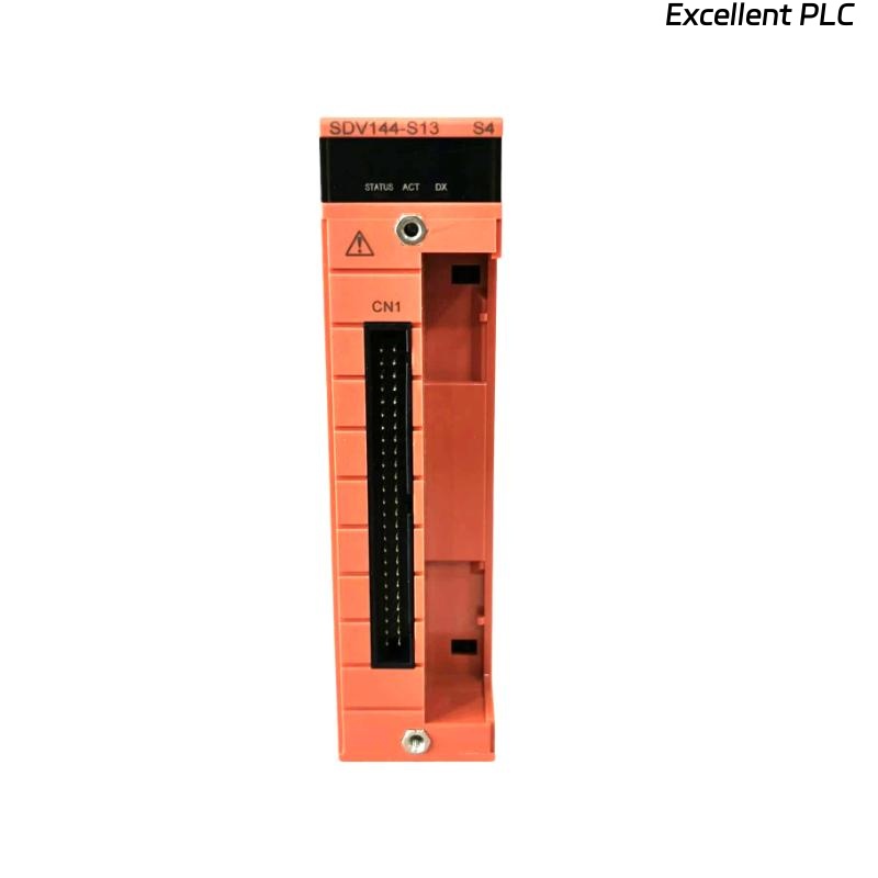
- SDV144-S13/D4A00 Digital Input Module Overview
- Typical Applications of the SDV144-S13/D4A00 Module
- Key Features of the Digital Input Module
- Installation Planning and Risk Assessment
- Installation Environment Requirements
- Input Signal Requirements
- Pre-Installation Inspection
- SDV144-S13/D4A00 Installation Guide
- Digital Input Wiring Practices
- Grounding and Shielding Recommendations
- SDV144-S13/D4A00 Setup Procedure
- Input Channel Mapping
- System Configuration Verification
- Signal Verification Testing
- Commissioning Workflow
- Operational Validation
- Maintenance Recommendations
- Real Commissioning Case
- FAQ
SDV144-S13/D4A00 Digital Input Module Overview
The Yokogawa SDV144-S13/D4A00 Digital Input Module is designed for high-reliability signal acquisition in safety and process control applications. The module receives field status signals from switches, relays, limit switches, emergency shutdown contacts, and other digital devices.
Typical Applications of the SDV144-S13/D4A00 Module
- Emergency Shutdown Systems (ESD)
- Fire and Gas Systems
- Turbine Protection Systems
- Compressor Control Systems
- Plant Interlock Monitoring
- Process Safety Systems
Key Features of the Digital Input Module
- High-speed signal acquisition
- Industrial noise immunity
- Channel isolation design
- Safety system compatibility
- Continuous signal monitoring
Installation Planning and Risk Assessment
Before installation, engineers should verify all field devices and ensure the System Configuration matches project documentation.
- Review I/O allocation drawings
- Verify terminal assignments
- Inspect field cable routes
- Confirm cabinet space availability
- Prepare commissioning procedures
Installation Environment Requirements
- Clean control cabinet environment
- Stable operating temperature
- Low vibration exposure
- Proper ventilation
- Adequate EMC protection
Input Signal Requirements
- Verify field signal voltage
- Inspect dry contact conditions
- Confirm signal polarity
- Validate cable continuity
- Check insulation resistance
Pre-Installation Inspection
- Verify module model number
- Inspect connectors
- Check terminal integrity
- Review installation drawings
- Inspect shipping condition
SDV144-S13/D4A00 Installation Guide
- Disconnect cabinet power.
- Insert the module into the designated slot.
- Lock the retaining mechanism.
- Connect terminal assemblies.
- Verify module seating.
- Inspect mechanical stability.
Digital Input Wiring Practices
- Use shielded signal cables
- Separate signal and power wiring
- Maintain cable identification
- Verify terminal torque values
- Avoid unnecessary cable splices
Grounding and Shielding Recommendations
- Single-point shield grounding
- Minimize EMI exposure
- Maintain cabinet bonding
- Avoid multiple ground paths
SDV144-S13/D4A00 Setup Procedure
INSTALL MODULE
VERIFY TERMINAL CONNECTIONS
CHECK FIELD SIGNALS
LOAD CONFIGURATION DATABASE
VALIDATE CHANNEL STATUS
SAVE CONFIGURATION
Input Channel Mapping
- Emergency stop contacts
- Pressure switch inputs
- Limit switch monitoring
- Fire and gas contacts
- Process interlock signals
System Configuration Verification
- Input address validation
- Signal assignment review
- Logic verification
- Database synchronization
- Alarm configuration check
Signal Verification Testing
- Contact simulation testing
- Signal transition verification
- Alarm activation testing
- Input response validation
- Logic execution review
Commissioning Workflow
- Verify hardware installation.
- Validate input signals.
- Confirm alarm functionality.
- Perform logic testing.
- Execute integrated system testing.
Operational Validation
- Input stability monitoring
- Alarm history review
- Response time analysis
- Communication verification
Maintenance Recommendations
- Quarterly terminal inspection
- Annual cable testing
- Routine configuration backup
- Signal trend monitoring
Real Commissioning Case
During startup of a refinery emergency shutdown system, six digital input channels on an SDV144-S13/D4A00 continuously indicated active alarms.
- Measured signal voltage: 11.2VDC
- Expected voltage: 24VDC
- Channel diagnostics: Normal
- Field contacts: Healthy
The maintenance team initially suspected a faulty Digital Input Module. However, field measurements revealed excessive voltage drop caused by a loose marshalling cabinet terminal.
After tightening the connection:
- Signal voltage increased to 23.8VDC
- Input status normalized
- Alarm conditions cleared
- Commissioning completed successfully
We observed that poor terminal connections frequently create symptoms similar to module failures.
SDV144-S13/D4A00 Installation Guide FAQ
What types of signals can the SDV144-S13/D4A00 monitor?
The module is designed to acquire digital field signals such as switches, relays, interlocks, and emergency shutdown contacts.
Why should input voltage be measured during Setup?
Incorrect voltage levels can result in false alarms, unstable status indications, or missed signal transitions.
Is shielding important for Digital Input Module installation?
Yes. Proper shielding reduces electromagnetic interference and improves signal reliability.
Summary: Successful SDV144-S13/D4A00 Installation, Setup, and Commissioning require proper wiring, accurate signal voltage verification, robust grounding practices, and complete System Configuration validation.