

Yokogawa ADR541-P00 relay output module installation problems are usually related to load wiring mistakes, relay contact sizing errors, or incorrect System Configuration rather than module hardware defects. Proper Setup and Commissioning procedures are essential for achieving reliable control of solenoid valves, contactors, motor starters, and shutdown devices.
Contents
- ADR541-P00 Relay Output Module Overview
- Typical ADR541-P00 Applications
- ADR541-P00 Technical Specifications
- Installation Planning Strategy
- Installation Environment Requirements
- Relay Load Assessment
- Pre-Installation Inspection
- ADR541-P00 Installation Guide
- Relay Output Wiring Practices
- Output Circuit Protection Design
- ADR541-P00 Setup Procedure
- System Configuration Verification
- Commissioning Workflow
- Relay Output Validation
- Maintenance Recommendations
- Real Commissioning Case
- FAQ
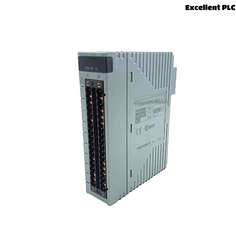
ADR541-P00 Relay Output Module Overview
The Yokogawa ADR541-P00 Relay Output Module provides 16 relay output channels and supports various industrial control applications. The module can switch both AC and DC loads and supports pulse-width and time-proportioning output functions. It is designed for use in high-reliability industrial control systems. :contentReference[oaicite:0]{index=0}
Typical ADR541-P00 Applications
- Emergency shutdown systems
- Process interlock control
- Motor starter control
- Solenoid valve switching
- Alarm annunciation systems
- Burner management systems
ADR541-P00 Technical Specifications
- 16 relay output channels
- 24 to 110 VDC load voltage
- 100 to 240 VAC load voltage
- Maximum 2A resistive load per channel
- Relay response time ≤12 ms
- Relay switching life: 100,000 operations
- Isolation between output and system circuits
The ADR541-P00 supports both resistive and inductive loads and provides relay isolation suitable for industrial automation environments. :contentReference[oaicite:1]{index=1}
Installation Planning Strategy
- Review output loading calculations
- Verify relay contact ratings
- Confirm cabinet capacity
- Inspect field device specifications
- Prepare commissioning procedures
Installation Environment Requirements
- Stable cabinet temperature
- Low vibration levels
- Proper ventilation
- Controlled humidity
- EMI protection measures
Relay Load Assessment
Before installation, verify actual field loads.
| Load Type | Maximum Rating |
|---|---|
| 24VDC Resistive | 2.0A/Channel |
| 24VDC Inductive | 0.6A/Channel |
| 220VAC Resistive | 2.0A/Channel |
| 220VAC Inductive | 1.0A/Channel |
Exceeding relay ratings can significantly reduce relay contact life. :contentReference[oaicite:2]{index=2}
Pre-Installation Inspection
- Verify model number
- Inspect terminals
- Check relay contacts
- Inspect mounting hardware
- Review wiring drawings
ADR541-P00 Installation Guide
- Disconnect system power.
- Insert the Relay Output Module into the designated slot.
- Secure locking mechanisms.
- Connect output terminals.
- Verify mechanical stability.
- Inspect terminal assignments.
Relay Output Wiring Practices
- Separate AC and DC wiring
- Use properly rated cables
- Verify relay contact polarity
- Apply terminal identification
- Inspect wiring continuity
Output Circuit Protection Design
- Install fuses for field loads
- Use surge suppressors
- Apply flyback diodes for DC coils
- Install RC snubbers for AC inductive loads
- Verify short-circuit protection
ADR541-P00 Setup Procedure
INSTALL MODULE
VERIFY TERMINALS
CHECK LOAD RATINGS
LOAD CONFIGURATION
ENABLE OUTPUT CHANNELS
SAVE PARAMETERS
System Configuration Verification
- Output mapping review
- Logic assignment verification
- Address validation
- Database synchronization
- Alarm configuration review
Commissioning Workflow
- Verify installation.
- Check output assignments.
- Perform relay switching tests.
- Validate field device operation.
- Complete integrated system testing.
Relay Output Validation
- Contact switching verification
- Output response measurement
- Load current monitoring
- Relay operation testing
Maintenance Recommendations
- Annual relay testing
- Terminal torque inspections
- Output current trending
- Routine configuration backup
Real Commissioning Case
During commissioning of a refinery burner management system, four field solenoids controlled by an ADR541-P00 failed to energize.
- Output command status: Active
- Relay response: Normal
- Measured load current: 0A
- Supply voltage: 110VAC
Initial assumptions focused on relay output failure. However, detailed engineering analysis revealed an incorrectly installed fuse block upstream of the field devices.
After correcting the wiring:
- Load current increased to 0.42A
- Solenoids energized correctly
- Relay outputs performed normally
- Commissioning completed successfully
We observed that field power distribution errors frequently mimic relay output module failures.
ADR541-P00 Installation Guide FAQ
How many relay outputs does the ADR541-P00 provide?
The module provides 16 relay output channels for industrial control applications. :contentReference[oaicite:3]{index=3}
Can the ADR541-P00 switch both AC and DC loads?
Yes. The module supports 24-110VDC and 100-240VAC load voltages within specified ratings. :contentReference[oaicite:4]{index=4}
Why should inductive loads be protected?
Inductive loads generate voltage spikes that can shorten relay contact life if suppression devices are not installed.
Summary: Successful ADR541-P00 Installation Guide implementation requires proper relay load sizing, accurate field wiring, effective surge protection, and complete System Configuration validation.