

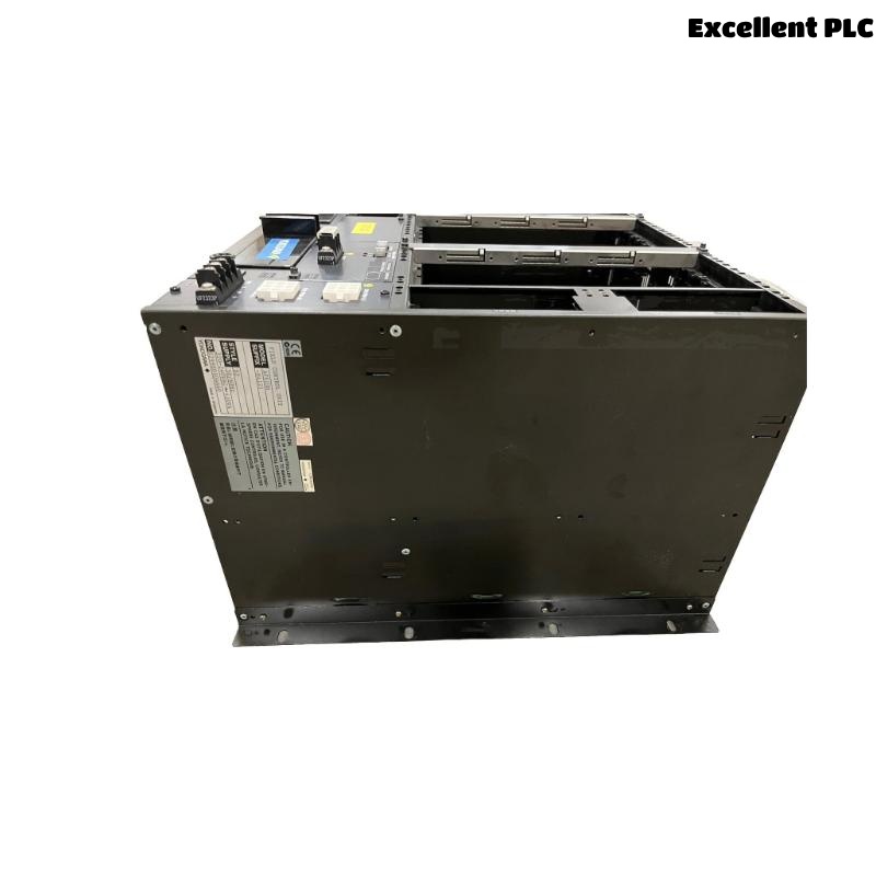
The Yokogawa AFS40S Field Control Unit (FCU) is a cabinet-mounted single-controller processor used in CENTUM VP and CENTUM CS 3000 Distributed Control Systems with the Field Control I/O (FIO) architecture. The controller performs continuous process control, sequence execution, alarm management, interlocking, and communication with distributed FIO node units through the ESB bus while exchanging plant information over the redundant V net control network. As a non-redundant controller, the AFS40S depends on stable hardware, communication links, and power supplies to maintain uninterrupted plant operation. A systematic troubleshooting methodology enables maintenance personnel to rapidly identify faults, restore controller functionality, and minimize production downtime.
Contents
- 1. Understanding AFS40S Fault Conditions
- 2. Common Failure Symptoms
- 3. Typical Causes of Controller Faults
- 4. Initial Hardware Inspection
- 5. Power System Verification
- 6. Startup Failure Diagnostics
- 7. FIO and ESB Bus Communication Diagnostics
- 8. Controller Diagnostic Analysis
- 9. Recommended Troubleshooting Workflow
- 10. Corrective Actions
- 11. Functional Recovery Verification
- 12. Preventive Maintenance
- 13. Real Industrial Maintenance Case
- 14. Frequently Asked Questions
Understanding AFS40S Fault Conditions
The AFS40S functions as the processing core of a Field Control Station, executing control applications and exchanging data with FIO node units through the ESB bus. Because the controller is non-redundant, failures involving the processor, communication interfaces, power supplies, or environmental conditions may directly interrupt plant control.
Typical controller faults include startup failures, ESB bus communication interruptions, FIO node communication loss, firmware incompatibility, application download failures, battery degradation, hardware malfunctions, and abnormal cabinet environmental conditions.
Common Failure Symptoms
- Controller fails to start
- Unexpected controller restart
- FIO node communication timeout
- ESB bus communication failure
- Application download failure
- Controller hardware alarm
- Battery backup alarm
- House Keeping environmental alarm
Typical Causes of Controller Faults
- Power supply instability
- Damaged ESB bus communication cables
- Loose communication connectors
- Incorrect FIO node configuration
- Controller hardware malfunction
- Firmware incompatibility
- Backup battery deterioration
- Cabinet overheating or ventilation failure
Initial Hardware Inspection
- Inspect controller status LEDs.
- Verify processor module installation.
- Check ESB bus communication cables.
- Inspect power supply indicators.
- Verify cabinet cooling fans and ventilation.
Power System Verification
Stable power is required to ensure reliable controller startup and uninterrupted process control.
- Verify controller input voltage.
- Inspect power supply outputs.
- Check circuit protection devices.
- Measure voltage stability.
- Review power-related alarm history.
Startup Failure Diagnostics
- Verify startup sequence completion.
- Inspect controller diagnostic indicators.
- Review startup alarm messages.
- Confirm firmware compatibility.
- Verify controller application integrity.
FIO and ESB Bus Communication Diagnostics
- Inspect ESB bus communication cables.
- Verify communication connector integrity.
- Review FIO diagnostic information.
- Check communication error counters.
- Confirm all FIO node units remain online.
Controller Diagnostic Analysis
| Observed Condition | Possible Diagnosis |
|---|---|
| Controller will not start | Power supply or processor hardware fault |
| Unexpected restart | Power disturbance or controller malfunction |
| FIO communication failure | ESB communication cable or interface problem |
| Battery alarm | Backup battery replacement required |
| House Keeping alarm | Cabinet environmental monitoring issue |
Controller diagnostic logs should always be reviewed before replacing controller hardware.
Recommended Troubleshooting Workflow
VERIFY POWER SUPPLY
CHECK CONTROLLER STATUS
VERIFY STARTUP
CHECK ESB BUS COMMUNICATION
VERIFY FIO NETWORK
VERIFY V NET COMMUNICATION
REVIEW DIAGNOSTIC LOGS
IDENTIFY ROOT CAUSE
IMPLEMENT CORRECTIVE ACTION
VERIFY SYSTEM RECOVERY
A structured troubleshooting workflow minimizes maintenance time and reduces unnecessary replacement of controller components.
Corrective Actions
- Restore stable power supplies.
- Replace damaged ESB communication cables.
- Reconnect loose communication connectors.
- Correct FIO node configuration.
- Reload controller applications.
- Replace backup battery when required.
- Replace controller hardware only after complete diagnostics.
Functional Recovery Verification
- Verify successful controller startup.
- Confirm stable ESB bus communication.
- Validate FIO node communications.
- Review controller diagnostic information.
- Monitor stable process operation under normal load.
Preventive Maintenance
- Inspect ESB communication wiring regularly.
- Review controller diagnostic logs periodically.
- Replace backup batteries according to maintenance schedules.
- Maintain controller configuration backups.
- Inspect cabinet ventilation and House Keeping alarms.
Real Industrial Maintenance Case
At a petrochemical production facility, operators reported intermittent communication loss between an AFS40S controller and several FIO node units.
Initial investigation suggested a controller processor fault. However, maintenance personnel found that one ESB bus connector had become partially loose because of prolonged cabinet vibration.
After securing the connector:
- All FIO node units re-established communication.
- Communication timeout alarms disappeared.
- Controller diagnostics returned to normal.
- The control system resumed stable production without replacing the controller.
This maintenance case demonstrates that communication wiring and ESB bus connections should always be inspected before replacing processor hardware.
Frequently Asked Questions
Why does the AFS40S fail to start?
Typical causes include unstable power supplies, controller hardware faults, firmware incompatibility, corrupted application files, or improper startup procedures.
What causes communication loss with FIO node units?
Common causes include damaged ESB communication cables, loose connectors, incorrect node configuration, interface failures, or communication network problems.
When should an AFS40S controller be replaced?
Controller replacement should only be considered after verifying power supplies, ESB communication wiring, firmware compatibility, application integrity, battery condition, and cabinet environmental conditions.
Summary
Effective troubleshooting of the Yokogawa AFS40S Field Control Unit requires systematic verification of power integrity, controller startup, ESB bus communications, FIO network status, diagnostic information, and hardware condition. Following a structured troubleshooting methodology helps restore stable process control, minimize downtime, and prevent unnecessary hardware replacement.