 Excellent PLC


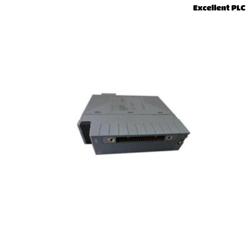
The Yokogawa ASD143 Digital Input Module is a 16-channel isolated digital input module used in Yokogawa CENTUM VP and CENTUM CS 3000 Distributed Control Systems (DCS). The module accepts NAMUR (IEC 60947-5-6) compatible input signals from proximity switches, limit switches, contact devices, and intrinsically safe field instruments. Because the ASD143 is responsible for monitoring field equipment status, failures affecting the module, wiring, or field devices may result in incorrect process indications, alarm malfunctions, or loss of digital status information.
Contents
- 1. Understanding Digital Input Faults
- 2. Common Failure Symptoms
- 3. Typical Causes
- 4. Initial Hardware Inspection
- 5. Field Wiring Verification
- 6. Field Device Inspection
- 7. Diagnostic Analysis
- 8. Recommended Troubleshooting Workflow
- 9. Corrective Actions
- 10. Functional Recovery Verification
- 11. Preventive Maintenance
- 12. Industrial Maintenance Case
- 13. Frequently Asked Questions
Understanding Digital Input Faults
The ASD143 continuously monitors field digital signals and transfers status information to the DCS. Faults may originate from failed NAMUR sensors, damaged field wiring, loose terminal connections, incorrect input configuration, grounding problems, insufficient signal current, or internal module failures. A structured troubleshooting process should determine whether the problem is located in the field device, wiring circuit, terminal assembly, or the ASD143 module itself.
Common Failure Symptoms
- Digital input remains permanently ON or OFF.
- Input status changes intermittently.
- DCS displays incorrect equipment status.
- Alarm signals do not operate correctly.
- Multiple channels fail simultaneously.
- Field device operation is normal, but no DCS indication appears.
- Input diagnostics report channel errors.
- Unexpected alarms occur.
Typical Causes
- Faulty NAMUR proximity sensor.
- Broken field cable.
- Loose terminal connection.
- Incorrect wiring polarity.
- Short circuit between channels.
- Poor grounding.
- Improper DCS configuration.
- Terminal assembly damage.
- Internal ASD143 hardware failure.
Initial Hardware Inspection
- Verify the ASD143 is correctly installed.
- Inspect module status indicators.
- Check terminal block installation.
- Inspect cabinet grounding.
- Verify cabinet temperature.
- Review DCS diagnostics.
Field Wiring Verification
- Inspect field cable continuity.
- Verify terminal numbers.
- Check wiring polarity.
- Inspect cable shielding.
- Verify insulation resistance.
- Inspect terminal tightness.
Field Device Inspection
- Verify NAMUR sensor operation.
- Measure sensor current output.
- Inspect proximity switch installation.
- Check limit switch contacts.
- Verify intrinsically safe barriers if installed.
- Confirm field device power supply.
Diagnostic Analysis
| Observed Condition | Possible Diagnosis |
|---|---|
| Single channel OFF permanently | Sensor failure or open circuit |
| Input always ON | Short circuit or incorrect wiring |
| Intermittent indication | Loose connection or unstable sensor |
| Multiple channels fail | Terminal block or power issue |
| Incorrect DCS indication | Configuration error |
Recommended Troubleshooting Workflow
CHECK DCS DIAGNOSTICS
VERIFY MODULE STATUS
INSPECT TERMINAL CONNECTIONS
CHECK FIELD WIRING
TEST NAMUR SENSOR
VERIFY CONFIGURATION
TEST INPUT CHANNEL
CONFIRM SYSTEM RECOVERY
Corrective Actions
- Tighten loose terminals.
- Replace damaged field wiring.
- Correct wiring polarity.
- Replace faulty NAMUR sensors.
- Repair grounding issues.
- Replace damaged terminal assemblies.
- Correct DCS configuration.
- Replace the ASD143 module if hardware failure is confirmed.
Functional Recovery Verification
- Verify correct input indication.
- Operate all field devices.
- Confirm alarm functionality.
- Review diagnostics.
- Verify signal stability.
- Monitor long-term operation.
Preventive Maintenance
- Inspect terminals periodically.
- Check cable insulation.
- Verify grounding.
- Review diagnostic history.
- Perform scheduled field tests.
- Maintain cabinet cleanliness.
Industrial Maintenance Case
At a refinery, operators reported that a tank high-level switch remained permanently OFF in the DCS even though the field switch had changed state. Maintenance technicians measured the NAMUR sensor current and discovered a broken conductor inside the field cable. After replacing the cable and verifying the terminal connections:
- The ASD143 channel responded normally.
- The alarm system operated correctly.
- DCS status indications were restored.
- No further communication issues occurred.
Frequently Asked Questions
Can the ASD143 accept standard 24 VDC digital inputs?
No. The ASD143 is specifically designed for NAMUR-compatible digital input signals according to IEC 60947-5-6 specifications.
Why does a channel remain ON continuously?
This may be caused by a short circuit, incorrect wiring, sensor failure, or improper configuration.
What should be checked before replacing the ASD143?
Verify field device operation, cable continuity, terminal connections, grounding, configuration, and sensor output before determining that the module has failed.
Summary
Effective troubleshooting of the Yokogawa ASD143 Digital Input Module requires systematic inspection of NAMUR sensors, field wiring, terminal assemblies, grounding, configuration parameters, and DCS diagnostics. Regular preventive maintenance and functional testing help ensure reliable digital signal acquisition and stable operation of Yokogawa CENTUM Distributed Control Systems.