| Company Information | ||||||||
| [email protected] | ||||||||
| Mobile | +8613666033393 | |||||||
| +8613666033393 | ||||||||
| 13666033393 | ||||||||
| Add | Room 1004, No. 62 Xiangxiu Li, Siming District, Xiamen City, Fujian Province, China | |||||||
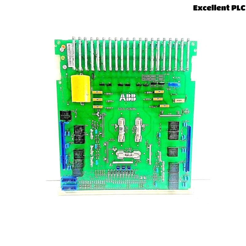
ABB SDCS-PIN-205 3ADT310500R1 Plc Module
- Product Details
- FAQs
- Related
- Contact Us
- Packing & Delivery
- Product Ratings
Product Introduction
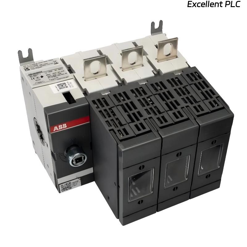
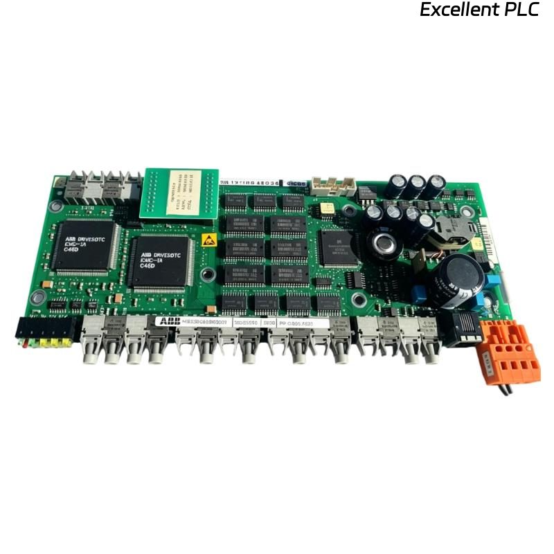
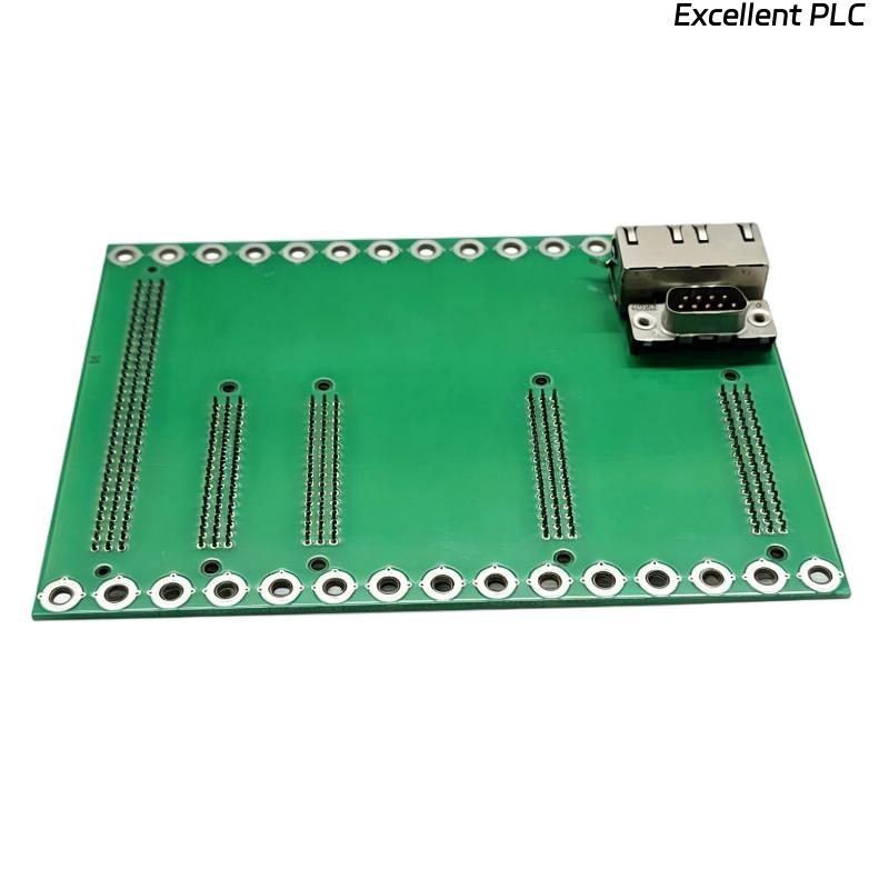
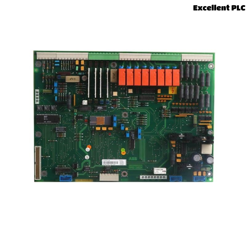
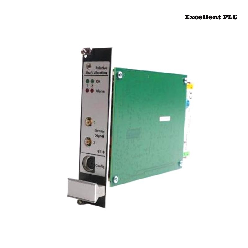
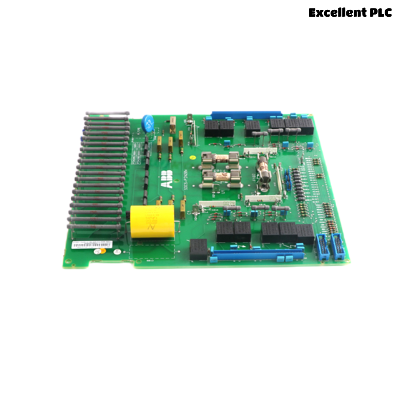
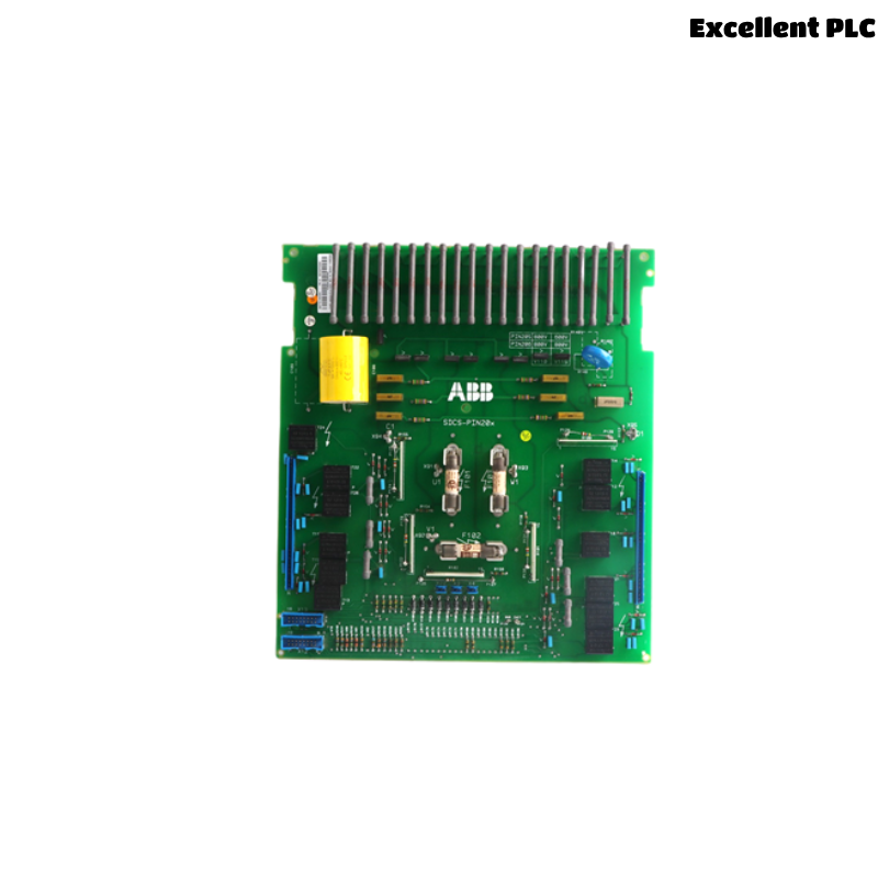
The ABB SDCS-PIN-205 (Part Number: 3ADT310500R1) is a reliable and high-performance Pulse Interface (PIN) board designed specifically for integration within ABB’s DCS 500 and DCS 600 series of DC drive systems. It serves as a crucial communication and interfacing component that connects peripheral modules and monitors pulse signals between the converter control system and the external fieldbus or I/O environment. The SDCS-PIN-205 acts as an intermediary for both analog and digital signal processing, ensuring precise operation of the drive and accurate data feedback for system regulation.
Due to its modular design, this board simplifies both system integration and future expansion. The SDCS-PIN-205 is widely recognized for its reliability, plug-and-play installation, and high compatibility with ABB’s industrial automation platforms.
Technical Specifications
| Parameter | Value |
|---|---|
| Product Name | SDCS-PIN-205 |
| Part Number | 3ADT310500R1 |
| Function | Pulse Interface Board for DCS drives |
| Supported Systems | DCS 500, DCS 600 |
| Input Voltage Range | 24 VDC (control side) |
| Signal Types | Analog and Digital Pulse Inputs |
| Connector Type | Multipin male connector interface |
| Communication Interface | Fiber optic and standard wiring support |
| Operating Temperature | 0°C to +55°C |
| Storage Temperature | -40°C to +70°C |
| Relative Humidity | 5% to 95% non-condensing |
| Mounting Type | DIN rail or chassis mounted |
| PCB Dimensions (W×H×D) | 170 mm × 100 mm × 20 mm |
| Weight | Approx. 0.35 kg |
| Compliance Standards | CE, RoHS |
Product Advantages
-
High Compatibility: Fully compatible with ABB DCS 500 and DCS 600 series drive systems, enabling direct replacement or integration.
-
Stable Pulse Transmission: Offers accurate pulse signal interfacing with low interference and high noise immunity.
-
Compact and Lightweight: With a slim form factor and light weight, it reduces the load and footprint in control cabinets.
-
Ease of Installation: Designed for easy plug-and-play replacement with guided terminal layouts.
-
Industrial-Grade Reliability: Withstands industrial environments thanks to its rugged design and robust temperature range.
-
Reduced Downtime: Proven ABB quality ensures long service life and high MTBF, minimizing maintenance needs.
-
Universal Signal Support: Interfaces both analog and digital signals, increasing its flexibility in control architectures.
-
Service-Friendly Design: Clear labeling, diagnostic LEDs, and accessible terminals make maintenance efficient.
Product Applications
-
Used in ABB DCS 500 and DCS 600 DC drive systems for interfacing control and power modules.
-
Ideal for industrial automation systems that require precise pulse signal processing.
-
Commonly found in:
-
Paper and pulp machinery
-
Steel and metal processing
-
Marine propulsion systems
-
Chemical and petrochemical plant automation
-
Mining conveyor control systems
-
Large motor control centers (MCCs)
-
Installation Instructions
-
Preparation: Power down the control system. Verify part number and version match your system requirements.
-
Mounting: Secure the SDCS-PIN-205 board to the DIN rail or chassis. Ensure the board is properly grounded.
-
Wiring: Connect all signal and power cables according to the drive manual. Use shielded cables for pulse signal lines.
-
Verification: After connection, inspect for any loose terminals or reversed polarity.
-
Power-Up and Test: Re-energize the system, then perform a drive diagnostic or test run to confirm the interface board is functioning.
-
Final Checks: Use system diagnostic tools to ensure that pulse signals are being properly received and transmitted.
Frequently Asked Questions (FAQs)
Q1: What does the SDCS-PIN-205 board primarily do?
A1: It interfaces pulse signals between the drive control unit and external systems, ensuring accurate timing and communication.
Q2: Can this board be used in systems other than ABB DCS drives?
A2: It is designed specifically for ABB’s DCS 500/600 systems, and use in other systems is not recommended unless verified by ABB.
Q3: What happens if this board fails?
A3: Pulse signal communication will be interrupted, potentially halting drive functions. Replacement or repair is advised immediately.
Q4: Is this board hot-swappable?
A4: No. Power must be disconnected before installing or replacing the board.
Q5: How can I identify a malfunction?
A5: Indicators such as drive alarms, irregular pulse reception, or diagnostic LED errors may signal board issues.
Q6: Can the SDCS-PIN-205 be upgraded with firmware?
A6: No, this is a hardware interface board with no upgradeable firmware.
Q7: What are the signs of board wear or damage?
A7: Burn marks, degraded connectors, or intermittent signal transmission suggest board failure.
Q8: Are there special tools required for installation?
A8: Standard tools such as screwdrivers and crimpers are sufficient. Follow ESD safety procedures.
Q9: How often should the board be inspected?
A9: Periodic visual inspections every 6-12 months are recommended in harsh environments.
Q10: Can I replace this board myself?
A10: Yes, if you are a trained technician or follow ABB’s installation manual. Otherwise, consult ABB service personnel.
Recommended Related Models (Same Series or Function)
-
SDCS-PIN-26 – Advanced pulse interface for specialized DCS applications
-
SDCS-PIN-21 – Pulse input board compatible with legacy systems
-
SDCS-CON-2 – Converter board for signal conditioning in DCS drives
-
SDCS-PIN-51 – Fiber optic version for enhanced isolation
-
SDCS-IOB-22 – Input/output board for auxiliary signal handling
-
SDCS-PIN-41 – High-speed version for fast pulse processing
Other Popular ABB Models (With Specifications)
| Model | Function | Voltage | Dimensions (mm) | Weight (kg) |
|---|---|---|---|---|
| SDCS-CON-2 | Converter Interface Board | 24 VDC | 150×95×20 | 0.30 |
| SDCS-PIN-51 | Fiber Optic Pulse Interface | 24 VDC | 170×100×22 | 0.33 |
| SDCS-IOB-22 | Digital/Analog I/O Board | 24 VDC | 180×90×25 | 0.34 |
| SDCS-PIN-26 | High Isolation Pulse Interface | 24 VDC | 160×95×20 | 0.36 |
| SDCS-COM-8 | Communication Interface Board | 24 VDC | 190×110×30 | 0.38 |
| SDCS-FEX-1 | Fieldbus Expansion Module | 24 VDC | 160×80×25 | 0.32 |

| Company Information | ||||||||
| [email protected] | ||||||||
| Mobile | +8613666033393 | |||||||
| +8613666033393 | ||||||||
| 13666033393 | ||||||||
| Add | Room 1004, No. 62 Xiangxiu Li, Siming District, Xiamen City, Fujian Province, China | |||||||
Excellent PLC Co., Ltd. has a large number of brand new and original PLC and DCS spare parts, with more than 60 cooperative countries. All products are guaranteed for 1 year and delivered to you by high-quality express. We are committed to using the best products and the most favorable prices to meet the needs and friendship of our customers. We have won the trust of thousands of customers, including these excellent customers.
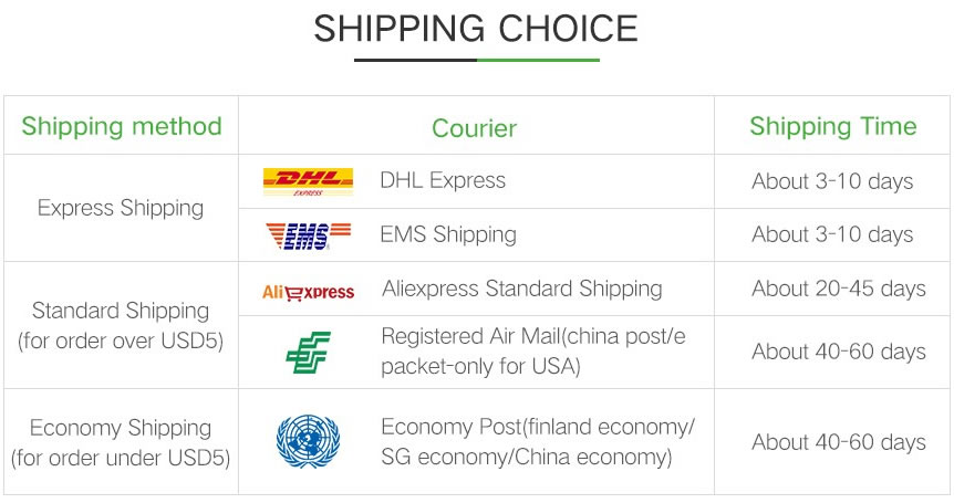
As for the delivery time, when we receive your order requirements, we will arrange for warehouse personnel to test and verify the products. After you place the order, we will send it to you within 24 hours.
Click to rate this post!
[Total: 0 Average: 0]