

1. Product Identification and Safety
1.1 Module Overview
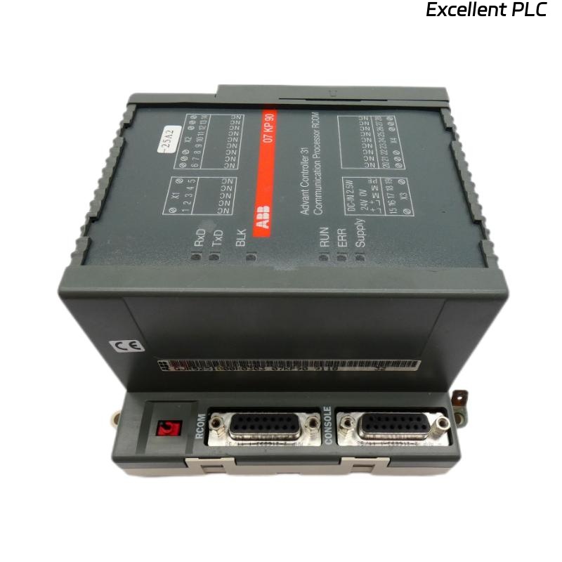
The ABB 07 AB 60 R1 (Article Number: GJV3074360R1) is a binary output module from ABB’s industrial automation portfolio, commonly used within the AC 800M controller family or as a remote I/O device on fieldbus networks. This module interfaces the control system to field actuators by providing electrically isolated switching signals.
Key Technical Data:
-
Function: Digital (Binary) Output Module
-
Number of Outputs: Typically 8 or 16 channels (verify via exact marking)
-
Output Type: Solid-state or Relay (Refer to datasheet for GJV3074360R1)
-
Output Voltage Range: Commonly 24V DC (for solid-state) or up to 230V AC (for relay versions)
-
Current Rating per Channel: Typically 0.5A to 2A (check nameplate)
-
Fieldbus Connection: Profibus DP, PROFINET, or other, via separate coupler module.
-
Isolation: Channel-to-channel and channel-to-system isolation.
1.2 Critical Safety Instructions
⚠️ WARNING: Failure to follow these instructions can result in injury, equipment damage, or malfunction.
-
Hazardous Voltage: This module switches power to field devices. Always de-energize and lock out all power sources (logic and field power) before installation, wiring, or maintenance.
-
Qualified Personnel: Installation and maintenance must be performed by qualified electrical personnel familiar with applicable codes and safety practices.
-
ESD Precautions: The module contains static-sensitive components. Handle with care, use an ESD wrist strap, and do not touch connector pins.
-
Environmental Conditions: Install only in a protective enclosure (minimum IP20). Ensure ambient conditions are within specification: Temperature -25°C to +60°C, relative humidity 5-95% non-condensing.
2. Pre-Installation Procedure
2.1 Tools and Materials Required
| Item | Specification | Purpose |
|---|---|---|
| Torque Screwdriver | 0.5 – 0.6 N·m | Terminal and mounting screw tightening |
| Wire Strippers | For 0.25 – 2.5 mm² (AWG 23-14) | Preparing field wiring |
| Digital Multimeter (DMM) | CAT III 600V minimum | Verification and diagnostics |
| DIN Rail | 35 mm top-hat, standard | Mounting base |
| Slot Label | ABB order code: 3BSE042098R1 (optional) | Module identification |
| Shielded Fieldbus Cable | As per network type (e.g., Profibus) | Communication wiring |
2.2 Verification and Planning
Before starting, ensure you have:
-
The correct module (GJV3074360R1) for your application.
-
The compatible bus coupler (e.g., CI871, etc.) and power supply module for the station.
-
Reviewed the system layout drawing and point list to confirm the module’s assigned address and channel assignments.
-
Downloaded the latest Device Description File (GSD/GSDML) for this module and imported it into your engineering tool (e.g., ABB Control Builder, Siemens STEP 7).
3. Mechanical Installation
Step 1: Mount the DIN Rail and Bus Coupler
-
Securely mount a 35mm DIN rail to the back panel of the enclosure.
-
Mount the bus coupler module on the far left side of the rail. Press down until it snaps into place. Secure the end clamp.
-
Mount the system power supply module (if separate) next to the coupler.
Step 2: Install the 07 AB 60 R1 Module
1.  Unpack the module and inspect for physical damage.
2.  Position the module to the right of the previous module in the station.
3.  Hook the top of the module onto the DIN rail.
4.  Firmly press the bottom of the module against the rail until the plastic locking clip engages with a clear "click."
5.  Slide the module leftwards until its connector mates with the adjacent module. Ensure it is snug and aligned.
6.  Install the **end clamp** on the right side of the module and tighten the screw to secure the entire row of modules to the rail.
Important: Maintain a minimum clearance of 50 mm above and below the module for adequate airflow.
4. Electrical Wiring
4.1 Power Supply Connections
The module typically receives its internal logic power (5V/24V) via the backplane connector from the system power supply. No direct user connection is needed for logic power.
However, you must connect the field power that will be switched to the loads.
-
Identify the field power supply terminals on the module. These are often labeled as L+ (or +24V) and M (or 0V/Common) in groups for several channels.
-
Using wires of appropriate gauge (e.g., 1.0 mm²), connect the positive pole of your external 24V DC field supply to the L+ terminals.
-
Connect the negative pole of the same field supply to the M terminals.
-
Tighten all power terminal screws to 0.6 N·m.
4.2 Output Channel Wiring (Example for One Channel)
Terminal Designation (Typical):
- Qx  : Output signal for channel x (e.g., Q1, Q2...)
- M_x : Common/return for the corresponding channel group.

Wiring Procedure for a 24V DC Solenoid:
1.  ISOLATE THE FIELD POWER SUPPLY.
2.  Connect one wire of the solenoid coil to the terminal **Q1**.
3.  Connect the other wire of the solenoid coil to the associated common terminal **M1** (or a grouped M terminal).
4.  For a relay output type switching 230V AC, connect the live wire to **Q1** and the neutral wire to the device, returning from the device to the **neutral bus**.
5.  Always install a **protective device** (like a fuse 2-4A gG) in series with each output channel.
4.3 Fieldbus Communication Wiring
-
Connect the fieldbus cable from the previous module or coupler to the IN port of the 07 AB 60 R1 module.
-
If this is the last module in the station, attach the terminating resistor plug to the OUT port. If not, run a cable from the OUT port to the IN port of the next module.
-
Ensure the cable shield is properly grounded at the coupler end only to prevent ground loops.
4.4 Wiring Best Practices
-
Separation: Keep high-voltage power cables (>60V) separated from communication and low-voltage signal cables by at least 200 mm. Cross them at a 90-degree angle if necessary.
-
Strain Relief: Use cable ducts and ties to provide strain relief, ensuring no pull is exerted on the module terminals.
-
Labeling: Clearly label all wires at both ends according to the wiring diagram.
5. Initial Power-Up and Basic Check
Step-by-Step Startup
-
Final Visual Inspection: Verify all modules are correctly seated, all connectors are mated, and no loose tools or wires are present.
-
Apply Logic Power: Turn on the power supply for the controller and I/O station.
-
Observe LEDs:
-
The PWR or SF (System Fault) LED on the bus coupler should turn green, indicating a healthy station.
-
The 07 AB 60 R1 module may have a STATUS LED. A steady green light typically indicates it is correctly addressed and communicating.
-
A red or flashing LED indicates a fault (e.g., no configuration, bus fault). Consult Section 6.
-
-
Apply Field Power: Turn on the external 24V DC field power supply.
-
Online Connection: Connect your engineering PC to the control system. Go online and verify that the I/O station, including the 07 AB 60 R1 module, is correctly recognized and shows no diagnostic errors.
6. Diagnostics and Troubleshooting
| LED / Symptom | Possible Cause | Corrective Action |
|---|---|---|
| No LED lit on module | No backplane power | Check the system power supply module and its fuse. Ensure all modules are properly connected on the backplane. |
| STATUS LED flashing red | Module not configured, or wrong configuration downloaded. | Download the correct hardware configuration to the controller. Check the GSD file version and module address in the project. |
| BF (Bus Fault) LED lit on coupler | Bus communication failure (wrong baud rate, cable break, missing terminator). | Check cable integrity and termination. Verify the Profibus address set on the coupler matches the software configuration. |
| Output does not switch despite ‘ON’ command | Field power missing, blown fuse, wiring error, overload/short on channel. | 1. Measure voltage between L+ and M at the module. 2. Check the protective fuse for that channel. 3. Use a multimeter to check for a short circuit or overload at the load. |
| Erratic output behavior | Ground loop, EMI/RFI interference, insufficient load for solid-state output. | Verify single-point grounding of shield. Check if a minimum load (e.g., 5mA) is required for solid-state outputs and use a dummy load resistor if needed. |
7. Configuration Notes
While physical installation is complete, the module must be configured in the control system software.
-
In your project hardware configuration, add the module from the hardware catalog using its exact GSD/GSDML file.
-
Assign the correct Profibus/PROFINET node address. This address is usually set on the bus coupler, not the individual I/O module.
-
The module’s channels will appear in the process image. Map these outputs to variables in your control logic (e.g., in Function Block Diagram or Structured Text).
-
Commissioning Test: After downloading the configuration, use the “Force” or “Monitor” function in the software to manually turn each output ON and OFF, verifying the correct operation of each connected field device.
Note: For detailed, model-specific parameters and wiring diagrams, always consult the official ABB Data Sheet for GJV3074360R1 and the AC 800M I/O System Installation Manual.