

Author: Marcus Zhao, Senior Field Automation Engineer, 22 Years in ABB S800 I/O Systems
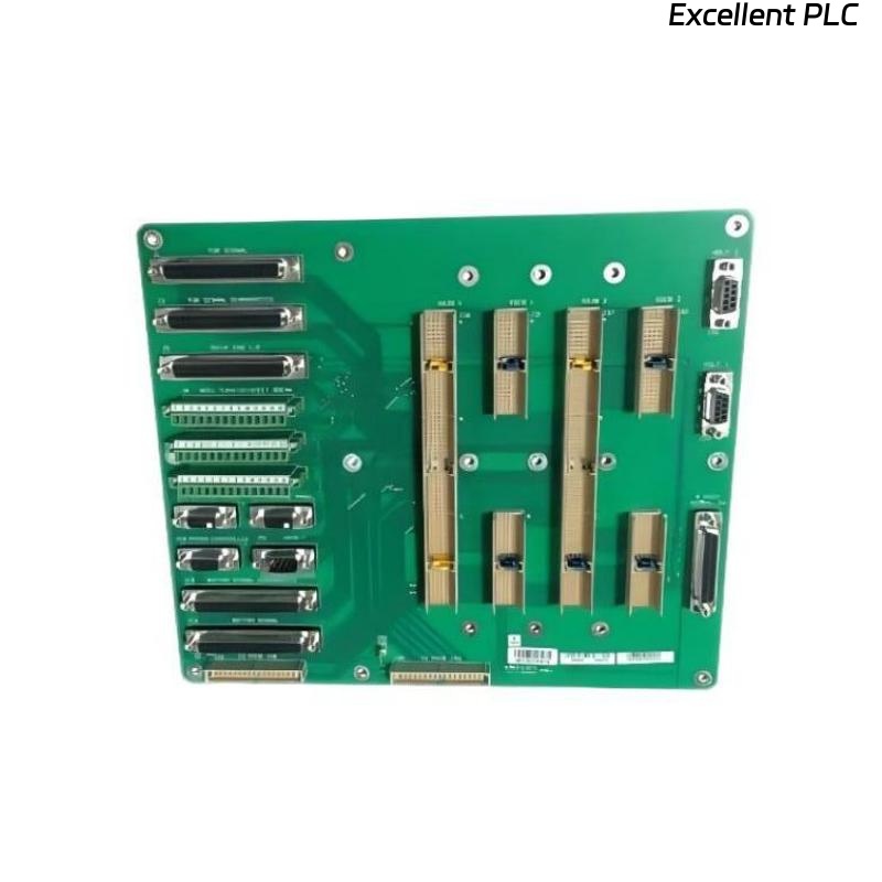
The ABB 07 BE 60 R1 6-slot rack is widely used in industrial automation for housing multiple S800 I/O modules. Proper installation and handling are critical to avoid mechanical stress, electrical failures, and communication issues.
This guide covers:
-
Rack preparation and site inspection
-
Mechanical installation step-by-step
-
Module insertion best practices
-
Wiring and grounding details
-
Post-installation verification and troubleshooting
-
Preventive maintenance and long-term management
-
Sample IEC/logic code for monitoring
1. Site Preparation
Before installing the 6-slot rack:
-
Rack Location: Ensure a flat, vibration-free surface. Avoid direct sunlight or high-temperature zones.
-
Environmental Conditions: Temperature: 0–55°C; Humidity: 5–95% RH (non-condensing)
-
Power Isolation: Completely cut off upstream DC or AC supply.
-
ESD Protection: Use wrist straps, mats, and ESD-safe gloves.
-
Document Existing Configuration: Record the slot usage, empty slots, and expected future expansions.
Field Tip: Mark each slot with a unique ID for easy future troubleshooting.
2. Mechanical Installation
Step-by-Step Guide:
-
Align Rack: Place the 6-slot frame on the mounting surface, ensuring mounting holes match pre-drilled supports.
-
Secure Base: Fasten rack using M6 screws, torque ~5–6 Nm. Ensure rack is level.
-
Backplane Inspection: Check for bent pins or contamination. Clean with IPA if necessary.
-
Insert Blank/Module End Plates: Install 1–2 blank panels if initial module count <6 to maintain airflow and prevent dust ingress.
-
Check Rack Latches: Ensure latch mechanisms move freely and lock securely.
-
Verify Clearance: Maintain minimum 50mm clearance for cables, 100mm for airflow above the rack.
3. Module Installation in Rack
Best Practices:
-
Insert modules vertically, gently aligning backplane pins.
-
Do not force or twist the module.
-
Tighten terminal screws evenly (torque ~0.4–0.5 Nm).
-
Route cables in assigned slots to prevent cross-talk or mechanical interference.
-
Label each module and its slot in the rack diagram.
Field Tip: Installing high-current outputs next to sensitive analog modules? Leave at least one blank slot in between for thermal and electromagnetic isolation.
4. Wiring & Grounding
-
Field Wiring:
-
Use twisted pair for digital signals to reduce EMI.
-
Keep analog and digital wiring separated by at least 50mm.
-
Use ferrite beads or shielded cables where inductive loads are present.
-
-
Backplane Grounding:
-
Ensure all rack metal frames contact the backplane to maintain electrical continuity.
-
Verify ground with DMM: <0.2Ω between rack frame and protective earth.
-
-
Power Distribution:
-
DC/AC busbars must be tightened properly to prevent arcing.
-
For high-current modules, use dedicated wiring to avoid voltage drops.
-
Example Check with Logic:
5. Post-Installation Verification
-
Power-Up: Apply voltage gradually, monitor LEDs on rack and modules.
-
Backplane Communication: Use built-in diagnostics or PLC to check module recognition.
-
Channel Verification: For each module, perform functional tests with actual loads.
-
Thermal Monitoring: Use infrared thermometer or thermal camera to scan rack after 15–30 minutes.
Sample IEC Verification Routine:
6. Troubleshooting Common Issues
| Symptom | Likely Cause | Suggested Action |
|---|---|---|
| Module not recognized | Backplane misalignment | Re-seat module, inspect pins |
| Intermittent outputs | Loose terminal screws | Retorque to spec |
| Overheating | Poor airflow | Insert blank panels, increase clearance |
| EMI interference | Adjacent high-current modules | Shield cables, increase separation |
Pro Tip: Start troubleshooting at power and grounding first; >50% of field faults trace back here.
7. Maintenance and Preventive Tips
-
Inspect rack mechanically every 6–12 months
-
Clean dust from slots and vents
-
Monitor ambient temperature, airflow, and vibration
-
Check terminal torque and grounding continuity
-
Keep a log of module replacement history, rack configuration, and serial numbers
8. Expansion and Future-Proofing
-
Document each empty slot as “available” in system software
-
Pre-plan airflow and spacing for anticipated future modules
-
Ensure blank panels or expansion spacers are installed to maintain thermal balance
-
Use consistent labeling and cable management to reduce human error
9. Field Notes & Practical Advice
-
Treat the rack as a system component, not just a frame
-
Correct installation reduces intermittent faults, extends module life, and prevents costly downtime
-
Detailed logging and preventive checks save hours in troubleshooting