

Author: Daniel Chen, Lead Field Automation Engineer, 19 Years ABB S800 Experience
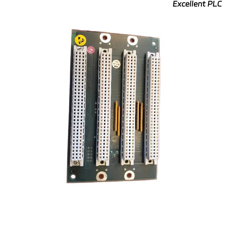
The ABB 07 BR 61 R1 coupler acts as the communication bridge between I/O modules and controllers. Field failures are often due to installation errors, wiring issues, or backplane contact problems. This guide emphasizes practical, step-by-step procedures for installation, troubleshooting, and repair.
1. Site Preparation
-
Power Isolation: Ensure rack power is completely OFF.
-
Rack Inspection: Check mechanical supports, ventilation, and ambient conditions (0–55°C, non-condensing).
-
ESD Safety: Wrist strap, mat, and gloves mandatory.
-
Backplane Check: Look for bent or corroded pins. Clean with IPA.
-
Labeling: Document intended slot number and module serial.
Pro Tip: Couplers should always be installed before field I/O modules to prevent communication errors during startup.
2. Mechanical Installation Steps
-
Align the coupler with the backplane slot vertically.
-
Insert gently; avoid twisting.
-
Secure latches or screws; torque ~0.4–0.5 Nm.
-
Verify flush alignment with neighboring modules.
-
Leave blank panels adjacent if high-current or heat-sensitive modules are nearby.
Field Tip: Uneven insertion is a common cause of intermittent faults.
3. Electrical & Communication Setup
-
Wiring: Follow ABB recommended separation: analog vs digital, high-current vs signal cables.
-
Grounding: Check continuity from coupler metal frame to protective earth (<0.2Ω).
-
Backplane Voltages: Measure Vlogic, Vdrive, Vsense at connector.
Communication Test Code Example:
4. Initial Power-Up & Diagnostics
-
Gradual power application.
-
Observe LEDs:
-
Green steady: OK
-
Green blinking: Initialization
-
Red: Fault
-
Off: No power
-
-
Check module recognition using ABB S800 diagnostic software or PLC monitoring.
-
Functional test: toggle outputs, read inputs, verify field device response.
5. Common Faults & Field Repairs
| Symptom | Likely Cause | Recommended Action |
|---|---|---|
| Module not recognized | Backplane misalignment | Reseat module, inspect pins |
| Intermittent I/O | Loose terminal or connector | Retorque screws, clean contacts |
| Communication timeout | Incorrect wiring or termination | Check shielded cable, termination resistors |
| Red LED persists | Firmware mismatch | Update firmware, reset module |
| Field devices unresponsive | Address conflict | Verify PLC/coupler addressing |
Field Note: Over 60% of coupler faults originate from wiring or grounding issues rather than module failure.
6. Bench Diagnostics
-
DMM to check backplane voltages
-
Oscilloscope to verify communication signals
-
Test memory/parameter storage using read/write sequences:
7. Preventive Maintenance
-
Check coupling connections every 6 months
-
Inspect LEDs and backplane contacts
-
Clean dust accumulation
-
Monitor thermal profile, avoid hotspots >55°C
-
Document installation date, serial number, and functional verification results
Pro Tip: Using thermal imaging early after installation prevents hidden overheating issues that can damage adjacent modules.
8. Replacement Decision Guidelines
-
Single-channel failure → check wiring first, repair if necessary
-
Communication errors persist → replacement recommended
-
Damaged connectors → immediate replacement
-
Safety-critical applications → always replace instead of repair in-field