

Author: Emily Sun, Senior Automation Field Engineer, 21 Years ABB S800 Expertise
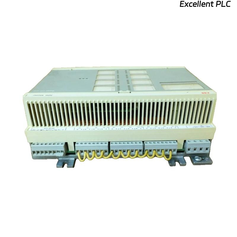
The ABB 07 BT 61 R1 control board manages complex I/O tasks and communicates with distributed modules in S800 racks. Proper installation and troubleshooting are critical to prevent communication errors, intermittent outputs, or complete system failure.
1. Pre-Installation Preparation
-
Power Isolation: Ensure main and auxiliary supplies are OFF.
-
ESD Protection: Wrist strap, mat, gloves mandatory.
-
Visual Inspection: Check for bent pins, damaged connectors, or prior repairs.
-
Rack Readiness: Confirm proper slot alignment, ventilation, and clearance.
-
Documentation: Record serial number, slot number, and associated modules.
Pro Tip: Photograph wiring and module layout for reference before installation.
2. Mechanical Installation Steps
-
Align the board vertically with the backplane slot.
-
Insert carefully, ensuring uniform contact with the backplane.
-
Secure screws with torque ~0.4–0.5 Nm.
-
Ensure flush alignment with adjacent modules.
-
Insert blank panels near high-current or heat-sensitive modules to prevent thermal issues.
3. Electrical & Wiring Guidelines
-
Separate analog, digital, and high-current cables to prevent EMI.
-
Grounding: metal frame to protective earth <0.2Ω.
-
Verify backplane voltage rails: Vlogic, Vdrive, Vsense.
-
Use shielded communication cables for Profibus/Modbus connections.
Example IEC Logic: Rack Voltage & Communication Verification
4. Power-Up & Functional Checks
-
Gradually apply power, monitor LED indicators:
-
Green steady: Normal operation
-
Green blinking: Initialization
-
Red: Fault
-
Off: No power
-
-
Use ABB S800 diagnostic software or PLC to verify board recognition and module communication.
-
Functional test: toggle outputs, read inputs, confirm actuator response.
5. Troubleshooting Common Issues
| Symptom | Likely Cause | Recommended Action |
|---|---|---|
| Board not recognized | Backplane misalignment | Reseat board, inspect connector pins |
| Intermittent communication | Loose terminals | Retorque screws, verify wiring |
| Field devices unresponsive | Address conflict | Verify module addressing in PLC/software |
| Red LED persists | Firmware mismatch | Update firmware using ABB S800 tool |
| Overheating | Poor airflow | Improve ventilation, insert blank panels |
Field Tip: Most failures occur due to wiring errors, poor grounding, or thermal stress rather than board defects.
6. Advanced Diagnostics & Maintenance
-
Voltage & Signal Checks: DMM for Vlogic/Vdrive/Vsense, oscilloscope for communication signals.
-
Firmware Verification: Ensure correct version and perform parameter memory test:
-
LED Pattern Monitoring: Confirm correct sequence during simulated start-up.
-
Thermal Checks: Infrared scan; surface temp should remain <55°C.
7. Preventive Maintenance Recommendations
-
Inspect board and backplane every 6–12 months.
-
Verify connectors, screws, and grounding integrity.
-
Monitor LEDs and thermal performance.
-
Log firmware updates, configuration changes, and field wiring modifications.
Field Tip: Early thermal monitoring prevents hidden failures that could propagate to connected modules.
8. Replacement vs. Repair Guidelines
-
Minor memory errors → reprogram and verify
-
Persistent communication faults → replace board
-
Damaged connectors or traces → mandatory replacement
-
Safety-critical systems → always replace in-field rather than attempt repairs