

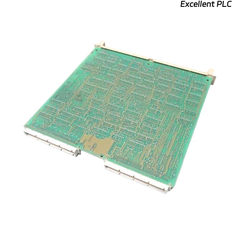
ABB 07 EA 63 R1 (GJV3074353R1)
Analog Input Module Fault Troubleshooting Guide
The ABB 07 EA 63 R1 (GJV3074353R1) is an analog input module widely used in ABB control systems. If the module reports a fault, shows no input values, or behaves abnormally, a structured troubleshooting approach is essential to minimize downtime and avoid unnecessary replacement.
This guide provides a step-by-step diagnostic procedure, including engineering logic examples, to help identify the root cause efficiently.
1. Verify Power Supply and Module Status
1.1 Power and Backplane Check
-
Confirm that the system power supply meets ABB specifications
-
Ensure the module is fully seated in the backplane
-
Inspect the slot for contamination or mechanical damage
1.2 LED Status Interpretation
Typical indications:
-
No LEDs ON → Power supply or backplane issue
-
Fault LED ON → Internal module fault or configuration error
-
Run/Status LED ON → Proceed to signal diagnostics
Diagnostic Logic (Pseudo Code)
2. Check Field Wiring and Signal Type
Incorrect wiring is one of the most common causes of analog input module faults.
Key Inspection Points:
-
Confirm signal type (4–20 mA or 0–10 V) matches module configuration
-
Verify correct polarity
-
Tighten terminals and inspect for damaged cables
-
Ensure proper shielding and single-point grounding
4–20 mA Loop Diagnostic Example
Engineering Note:
More than 70% of analog input issues originate from wiring or field devices rather than the module itself.
3. Validate Field Devices and Signal Source
To isolate the module from field-related issues:
-
Measure the signal directly using a multimeter
-
Inject a known test signal using a signal calibrator
-
Confirm the transmitter is powered and operating within range
Signal Injection Test Logic
If the injected signal is correct but not detected, proceed to configuration checks.
4. Review System Configuration and Channel Parameters
Configuration mismatches frequently cause module fault indications.
Verify the Following:
-
Correct module type (07 EA 63 R1) defined in the system
-
Channels enabled and assigned correctly
-
Proper input type selection (current or voltage)
-
Scaling, limits, and engineering units
Channel Enable Verification
⚠️ Common Configuration Errors:
-
Incorrect module revision selected
-
Incomplete configuration download
-
Firmware or system version incompatibility
5. Analyze System Diagnostics and Fault Messages
Use ABB engineering tools to inspect:
-
Module communication status
-
Channel-level diagnostic flags
-
Overrange or underrange alarms
Module Health Check
Diagnostic messages often provide direct guidance to the root cause.
6. Perform Channel and Module Isolation Tests
Isolation testing is critical for determining whether the fault is hardware-related.
Recommended Actions:
-
Swap input channels within the module
-
Move the signal to a known-good module
-
Replace the module temporarily with a tested spare
Root Cause Determination Logic
7. Check Environmental and Operating Conditions
Environmental factors can significantly impact analog input reliability.
Verify:
-
Ambient temperature and humidity within ABB limits
-
Absence of excessive vibration
-
Proper separation from high-noise electrical equipment
-
No visible signs of overheating or physical damage
8. When to Replace the Module
If all diagnostic steps have been completed and the fault persists:
-
The ABB 07 EA 63 R1 (GJV3074353R1) may have an internal hardware failure
-
Replacement or professional repair is recommended
-
Keeping a tested spare module is advised for critical systems
Conclusion
Troubleshooting the ABB 07 EA 63 R1 analog input module requires a systematic approach covering power, wiring, signal validation, configuration, and diagnostics. By following the steps outlined above and using isolation testing, engineers can accurately identify the fault source, reduce downtime, and avoid unnecessary component replacement.