

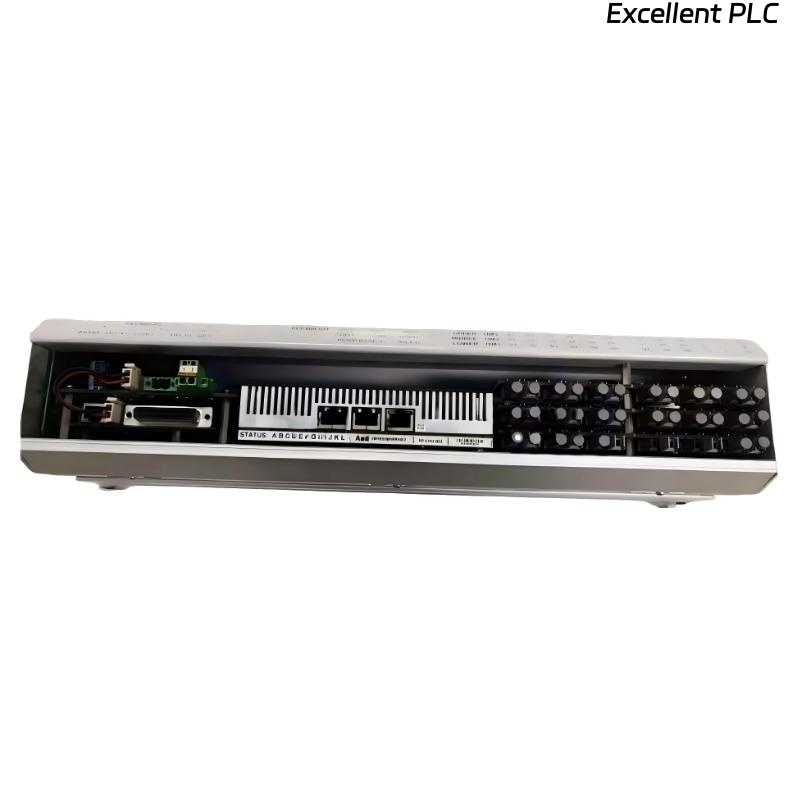
ABB 07 EA 64 R1 (GJV3074355R1)
What to Do When the System Reports an Error on the Analog Input Module
The ABB 07 EA 64 R1 (GJV3074355R1) is a high-performance analog input module used in ABB automation and control systems. When the control system reports a system error, it may indicate issues related to power, configuration, communication, signal integrity, or internal hardware faults.
This guide provides a structured troubleshooting methodology, including engineering logic examples, to help engineers quickly identify and resolve system-reported errors.
1. Identify the System Error Type
Before taking corrective action, determine how the error is reported:
-
Module fault alarm in the control system
-
Communication error or “module not responding”
-
Channel diagnostic alarms (overrange / underrange)
-
System status = NOT READY / ERROR
Initial Diagnostic Logic
Understanding the exact error message significantly reduces troubleshooting time.
2. Check Power Supply and Backplane Communication
System errors are often triggered by power or backplane issues.
Inspection Steps:
-
Verify that the rack power supply is stable
-
Confirm correct voltage levels
-
Ensure the module is firmly seated in the backplane
-
Inspect the slot for contamination or bent connectors
Power and Communication Check
If the system cannot communicate with the module, configuration and signal checks will be ineffective.
3. Verify Module Recognition and Configuration
A common cause of system errors is configuration mismatch.
Verify:
-
Correct module type defined: 07 EA 64 R1
-
Slot assignment matches the physical installation
-
Channels are enabled
-
Input type (4–20 mA / 0–10 V) is correctly selected
-
Scaling and limits are properly configured
Configuration Validation Logic
⚠️ Even a correct module with the wrong configuration will trigger system-level errors.
4. Analyze Channel Diagnostics and Signal Status
System errors may originate from one or more faulty channels.
Typical Channel-Related Causes:
-
Open current loop
-
Signal overrange or underrange
-
Incorrect wiring polarity
-
Short circuit
4–20 mA Signal Diagnostic Example
A persistent channel fault can escalate into a module or system error.
5. Test with Known-Good Signal Source
To separate field issues from module issues:
-
Disconnect the field device
-
Inject a calibrated test signal (e.g. 12 mA or 5 V)
-
Observe system response
Signal Injection Test Logic
If the system still reports an error with a known-good signal, the issue is likely not field-related.
6. Perform Module and Slot Isolation
Isolation testing is essential when system errors persist.
Recommended Actions:
-
Move the module to a different slot
-
Replace it with a known-good spare
-
Check whether the error follows the module or the slot
Root Cause Determination
7. Review Environmental and Operating Conditions
Environmental stress can cause intermittent or persistent system errors.
Check for:
-
Excessive temperature or humidity
-
Strong electrical noise nearby
-
Vibration or mechanical stress
-
Signs of overheating or physical damage
8. When to Replace the Module
If all checks have been completed and the system error remains:
-
The ABB 07 EA 64 R1 (GJV3074355R1) may have an internal failure
-
Replacement or professional repair is recommended
-
For critical applications, maintain a tested spare module
Conclusion
When a system reports an error on the ABB 07 EA 64 R1 analog input module, the root cause typically lies in power, configuration, communication, signal integrity, or hardware failure. By following a step-by-step diagnostic process and applying isolation testing, engineers can quickly determine whether corrective action, reconfiguration, or module replacement is required.
A structured troubleshooting approach minimizes downtime and ensures stable system operation.