

Contents
- Overview of the 07AI91 WT91 Module
- Function in ABB Automation Systems
- Preparation Before Installation
- Rack Mounting Instructions
- Analog Signal Wiring Guidelines
- System Startup and Module Detection
- Installation Best Practices
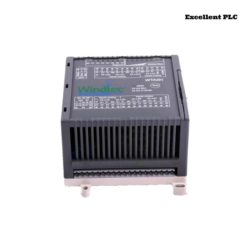
Overview of the 07AI91 WT91 Module
The ABB 07AI91 WT91 analog input module (GJR5251600R4202) is designed to collect analog measurement signals from industrial sensors and transmitters. These signals are converted into digital values that the control system can process for monitoring and automation control.
This module is commonly installed inside ABB control cabinets as part of the automation signal acquisition layer.
Function in ABB Automation Systems
Within ABB automation platforms, analog input modules provide the interface between field instruments and the controller. The 07AI91 WT91 module enables precise acquisition of industrial process variables.
Typical applications include:
- Temperature transmitter monitoring
- Pressure and flow measurement acquisition
- Process control feedback signals
- Industrial monitoring systems
Proper installation ensures accurate signal conversion and stable system performance.
Preparation Before Installation
Before installing the module, engineers should verify that the cabinet environment meets the recommended conditions.
- Operating temperature: 0°C to 50°C
- Relative humidity below 85%
- No condensation or water inside the cabinet
- Reliable cabinet grounding
Required installation tools:
- Insulated screwdriver
- Digital multimeter
- Wire stripping tool
- Anti-static wrist strap
Rack Mounting Instructions
Power Isolation
- Turn off power to the control cabinet.
- Confirm that the rack is completely de-energized.
Module Installation
- Locate the appropriate slot in the ABB rack.
- Align the module with the rack guide rails.
- Insert the module carefully until the backplane connector engages.
- Lock the module into place using the rack retention mechanism.
Proper engagement with the backplane connector ensures reliable communication with the controller.
Analog Signal Wiring Guidelines
Signal wiring must follow the official ABB system wiring diagram.
- Verify whether the signal type is current (4–20 mA) or voltage.
- Use shielded cables for analog signals.
- Separate analog wiring from high-power cables.
- Ensure terminals are tightened securely.
These practices help prevent noise interference and measurement errors.
System Startup and Module Detection
After completing the installation, power on the control system and verify that the module is recognized.
SYSTEM_BOOT
SCAN_INSTALLED_MODULES
DISPLAY_MODULE_STATUS
VERIFY_MODULE 07AI91
If the module appears in the hardware list and no faults are reported, the installation has been completed successfully.
Installation Best Practices
- Clearly label all analog input cables.
- Document module slot positions in system records.
- Ensure adequate cabinet ventilation.
- Perform periodic inspection of signal terminals.
Following these best practices helps maintain long-term reliability for ABB analog input modules such as the 07AI91 WT91.