

Technical Navigation
- Typical Fault Scenario
- Common Digital Input Signal Problems
- Field Diagnosis Workflow
- Testing Digital Input Channels
- Repair and Recovery Guidelines
- Maintenance Practices for Stable Operation
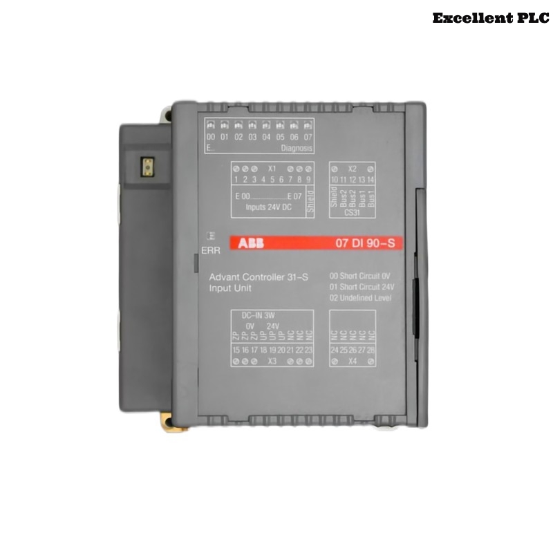
Typical Fault Scenario
The ABB 07DI90-S digital input module (GJR5250900R0202) is responsible for receiving binary signals from industrial sensors and switches. When faults occur in the signal path, the PLC may misinterpret equipment status or fail to trigger programmed automation logic.
Engineers working in the field may observe several abnormal behaviors:
- Digital input channels remain permanently ON or OFF.
- The PLC program does not react to physical switch operations.
- Input signals appear unstable or flicker intermittently.
- Alarm messages related to input module status appear in the PLC diagnostics.
- Machine safety interlocks fail to activate.
These symptoms typically indicate problems within the signal wiring, the field device, or the module input circuitry.
Common Digital Input Signal Problems
Digital input modules rely on stable electrical signals from sensors and switches. Several electrical faults may disrupt this communication.
- Short circuit between signal wires.
- Broken wire connections inside terminal blocks.
- Incorrect sensor power supply voltage.
- Electrical interference from nearby motor drives.
- Oxidized or loose terminal connections.
Signal instability often originates from wiring issues rather than internal module failure.
Field Diagnosis Workflow
A structured troubleshooting workflow helps isolate the root cause of digital input faults.
Inspection Stage
- Check whether the module LEDs indicate active input signals.
- Inspect wiring terminals for loose connections.
- Verify that sensors are receiving proper supply voltage.
Cable Verification
- Trace the cable path from the field device to the module.
- Inspect cable insulation and connectors.
- Ensure the cable shield is grounded correctly.
Cabinet Condition Check
- Look for moisture or dust inside the control cabinet.
- Verify cabinet temperature and airflow.
- Ensure grounding connections are secure.
Testing Digital Input Channels
Digital input channels can be verified using simple electrical measurements.
- Use a multimeter to measure input voltage at the terminal.
- Operate the connected switch or sensor manually.
- Observe whether the signal voltage changes correctly.
If the voltage changes but the PLC does not detect it, the module input channel may be defective.
Repair and Recovery Guidelines
Once the fault source has been identified, the following corrective actions may restore normal operation.
- Tighten loose terminal screws.
- Replace damaged signal cables.
- Correct wiring polarity and sensor supply voltage.
- Improve cable routing to reduce electrical interference.
- Replace the input module if internal circuitry has failed.
Ensure that any replacement module matches the part number GJR5250900R0202.
Maintenance Practices for Stable Operation
Preventive maintenance helps maintain reliable PLC input signal detection.
- Inspect field wiring connections during scheduled maintenance.
- Check terminal tightness periodically.
- Keep control cabinets clean and dry.
- Monitor PLC diagnostic logs for abnormal input behavior.
- Document any wiring modifications or module replacements.
By following these practices, engineers can ensure long-term reliability of the ABB 07DI90-S digital input module within industrial automation systems.