

Content Overview
- Introduction to the 07DI90-S Module
- Role in ABB PLC Control Architecture
- Pre-Installation Preparation
- Rack Mounting and Mechanical Installation
- Digital Input Wiring Configuration
- System Startup and Module Verification
- Practical Tips for Field Engineers
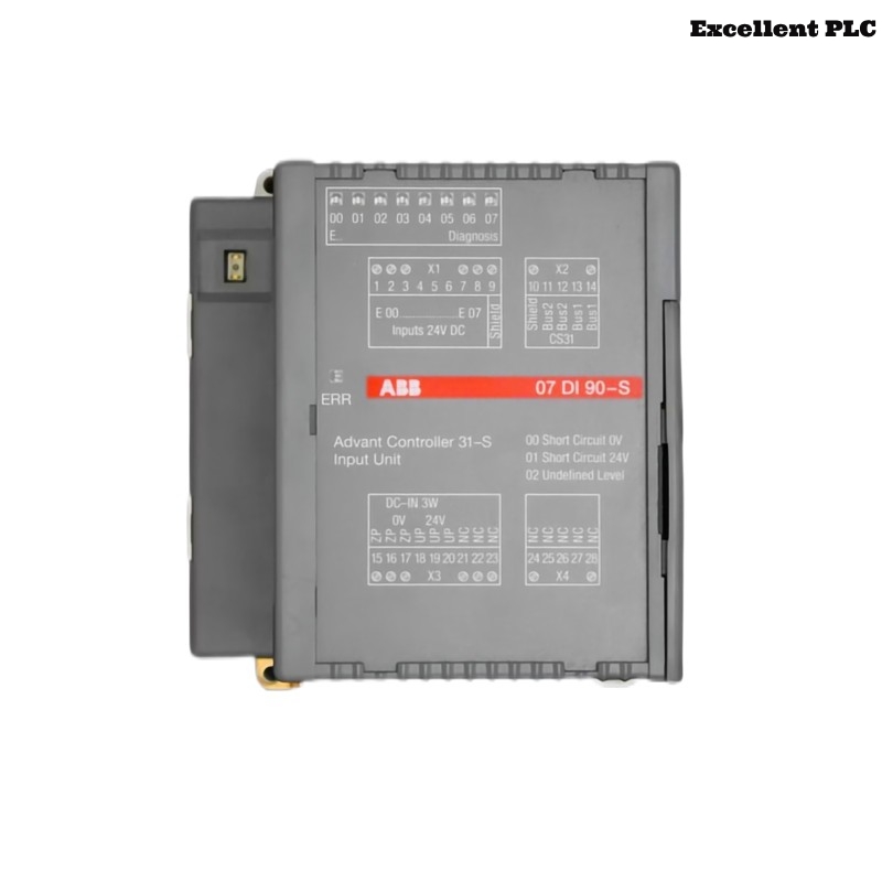
Introduction to the 07DI90-S Module
The ABB 07DI90-S digital input module (GJR5250900R0202) is designed to collect discrete input signals from industrial devices such as limit switches, push buttons, proximity sensors, and relay contacts. These field signals are transmitted to the PLC controller where they are processed for automation logic and safety control.
Proper installation ensures stable signal acquisition and prevents incorrect input readings that could affect system operation.
Role in ABB PLC Control Architecture
In ABB PLC systems, digital input modules form the interface between field devices and the central controller. The 07DI90-S module allows the PLC to detect the status of industrial equipment and react accordingly through programmed control logic.
Typical uses include:
- Machine status monitoring
- Safety interlock signals
- Position detection using limit switches
- Start/stop command inputs from operators
The module transmits these binary signals through the rack backplane to the PLC CPU.
Pre-Installation Preparation
Before installing the digital input module, engineers should verify that the control cabinet meets operational requirements.
- Ambient temperature between 0°C and 50°C
- Relative humidity below 85%
- Proper cabinet grounding
- No moisture or conductive dust inside the rack
Recommended tools:
- Insulated screwdriver
- Wire stripper
- Digital multimeter
- Anti-static protection strap
Using ESD protection helps avoid accidental damage to electronic components.
Rack Mounting and Mechanical Installation
Step 1 – Safety Isolation
- Switch off power to the control cabinet.
- Verify that the PLC rack bus voltage is fully disconnected.
- Ensure other modules are firmly installed.
Step 2 – Module Placement
- Locate the designated rack slot for the 07DI90-S module.
- Align the module with the guide rails of the rack.
- Slide the module into position until the connector engages.
- Secure the module using the rack locking system.
A secure mechanical connection ensures stable communication with the rack backplane.
Digital Input Wiring Configuration
Field devices must be wired according to ABB electrical diagrams for digital input modules.
- Verify correct voltage level for the digital input circuit.
- Ensure proper polarity when connecting sensor outputs.
- Use shielded cables in environments with electrical noise.
- Separate signal wiring from high-power motor cables.
These precautions reduce interference and ensure accurate signal detection.
System Startup and Module Verification
After completing installation and wiring, power up the PLC system and confirm that the module is detected correctly by the controller.
SYSTEM_BOOT
SCAN_IO_MODULES
DISPLAY_RACK_STATUS
VERIFY_MODULE 07DI90
CHECK_INPUT_CHANNEL_STATUS
If the controller identifies the module and no fault messages appear, the installation has been successfully completed.
Practical Tips for Field Engineers
- Label each digital input cable for easier maintenance.
- Document the rack slot number and module type.
- Check terminal screws periodically during maintenance.
- Monitor PLC diagnostic logs for input channel abnormalities.
Following these installation guidelines ensures reliable operation of the ABB 07DI90-S digital input module in industrial automation systems.