

Article Overview
- Introduction to the 07EA90 Module
- Role within ABB PLC Automation Systems
- Preparation Before Installation
- Hardware Mounting Instructions
- Analog Signal Wiring Recommendations
- System Startup and Verification
- Engineering Deployment Tips
Introduction to the 07EA90 Module
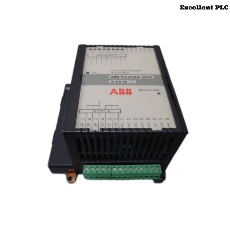
The ABB 07EA90 analog input module (GJR5251200R0101) is designed to collect analog signals from field devices and convert them into digital data that can be processed by ABB PLC controllers. Typical input signals include voltage and current values generated by industrial sensors.
Accurate installation is essential to maintain signal integrity and ensure that the automation system receives reliable measurement data.
Role within ABB PLC Automation Systems
Analog input modules play a vital role in process monitoring. The 07EA90 module enables PLC systems to measure and respond to continuously varying signals such as temperature, pressure, and flow.
Common industrial applications include:
- Process temperature monitoring
- Flow measurement systems
- Pressure monitoring in pipelines
- Level measurement in tanks
- Energy consumption monitoring
The module converts these physical measurements into digital values that can be used in PLC control algorithms.
Preparation Before Installation
Before installing the 07EA90 module, ensure the control cabinet environment meets ABB industrial standards.
- Ambient temperature between 0°C and 50°C
- Humidity level below 85%
- Stable and properly grounded control cabinet
- Shielded wiring available for analog signals
Recommended tools for installation:
- Insulated screwdriver set
- Wire stripping tool
- Digital multimeter
- Anti-static wrist strap
Hardware Mounting Instructions
Power Isolation
- Switch off the PLC rack power supply.
- Verify that the backplane voltage is completely disconnected.
- Confirm that adjacent modules remain properly seated.
Module Installation
- Identify the designated slot in the PLC rack.
- Align the 07EA90 module with the rack guide rails.
- Slide the module gently into the slot.
- Press firmly until the backplane connector engages.
- Secure the module using the rack locking mechanism.
Correct seating ensures stable electrical communication with the PLC backplane.
Analog Signal Wiring Recommendations
Proper wiring practices are essential for maintaining accurate analog signal readings.
- Use shielded cables for analog signal transmission.
- Separate signal cables from high-power electrical wiring.
- Verify correct polarity for current and voltage inputs.
- Ensure terminal connections are tight and secure.
- Ground cable shielding at the control cabinet grounding point.
These practices help reduce electromagnetic interference that could distort sensor readings.
System Startup and Verification
After completing installation and wiring, power on the PLC system and verify that the module is recognized.
SYSTEM_INITIALIZE
SCAN_RACK_CONFIGURATION
DETECT_MODULE 07EA90
CHECK_ANALOG_CHANNEL_STATUS
READ_INPUT_VALUES
If the system correctly detects the module and analog values are displayed, the installation has been completed successfully.
Engineering Deployment Tips
- Label all analog input channels clearly.
- Maintain detailed documentation for each wiring connection.
- Periodically inspect terminal blocks and cables.
- Monitor PLC diagnostic logs for abnormal signal readings.
Following these installation practices ensures stable and accurate performance of the ABB 07EA90 analog input module within industrial automation environments.