

Guide Outline
- Controller Overview
- Position in the Procontic PLC Architecture
- Site and Cabinet Preparation
- CPU Module Mounting Procedure
- Power Supply and Communication Setup
- Initial Startup and System Initialization
- Engineering Notes for Reliable Operation
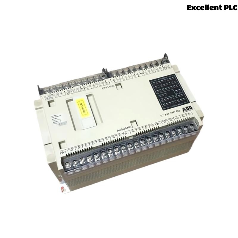
Controller Overview
The ABB 07KR240 / 07KR240dR1 central processing unit is a programmable logic controller designed for industrial automation within ABB Procontic control systems. The CPU processes control logic, manages input and output modules, and coordinates communication between field devices and the automation network.
This controller is commonly installed in control cabinets for manufacturing lines, process automation systems, and industrial machinery.
Position in the Procontic PLC Architecture
Within the ABB PLC architecture, the 07KR240 CPU functions as the main control unit responsible for:
- Executing PLC control programs
- Managing digital and analog I/O modules
- Handling communication between operator interfaces and field devices
- Monitoring system status and diagnostics
Proper installation ensures reliable coordination between the CPU and the connected modules.
Site and Cabinet Preparation
Before installing the PLC controller, ensure the control cabinet meets industrial environmental requirements.
- Ambient temperature between 0°C and 50°C
- Relative humidity below 85%
- Stable grounding of the control cabinet
- Protection from excessive vibration and dust
Recommended installation tools:
- Insulated screwdriver set
- Digital multimeter
- Anti-static wrist strap
- Industrial Ethernet or communication cables
CPU Module Mounting Procedure
Preparation
- Disconnect all power sources to the PLC rack.
- Verify that the rack backplane is not energized.
- Check that the mounting rail is properly grounded.
Installing the CPU Module
- Align the 07KR240 CPU with the DIN rail or mounting slot.
- Insert the module carefully until the backplane connector engages.
- Secure the module using the provided locking mechanism.
- Verify that the module is firmly seated and aligned with adjacent components.
A correct mechanical installation ensures stable communication between the CPU and I/O modules.
Power Supply and Communication Setup
After installing the CPU module, connect the required power and communication interfaces.
- Connect the recommended DC power supply to the CPU terminals.
- Verify polarity and voltage levels before powering up.
- Connect communication cables for programming or network integration.
- Route signal cables away from high-power electrical lines.
Correct cable routing reduces electromagnetic interference in the automation system.
Initial Startup and System Initialization
Once installation and wiring are complete, power on the PLC system and verify that the controller initializes properly.
SYSTEM_POWER_ON
INITIALIZE_CPU
SCAN_CONNECTED_MODULES
VERIFY_IO_CONFIGURATION
LOAD_CONTROL_PROGRAM
Successful initialization confirms that the CPU recognizes all connected modules and is ready to execute the control program.
Engineering Notes for Reliable Operation
- Label all cables and module slots clearly.
- Maintain updated documentation for the PLC configuration.
- Monitor CPU status LEDs for system health.
- Regularly back up PLC control programs.
- Keep the control cabinet clean and properly ventilated.
Following these practices helps ensure stable operation of the ABB 07KR240 PLC controller in industrial automation systems.