

Quick Navigation
- System Background
- Failure Scenario
- Symptom Pattern
- Diagnostic Approach
- Repair Strategy
- Preventive Measures
System Background
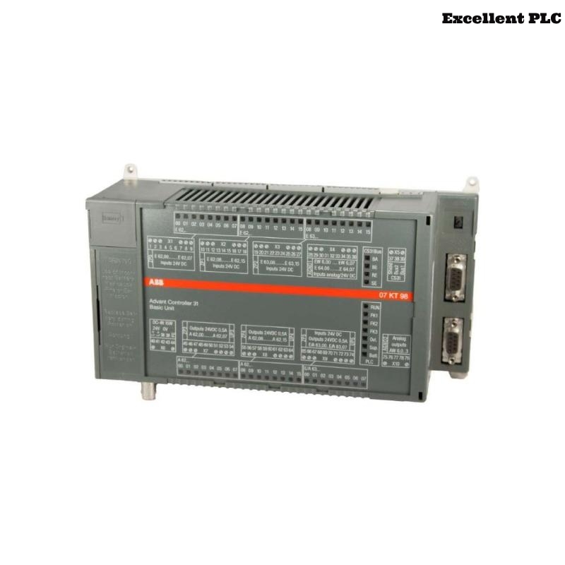
The ABB 07KT94 GJR5252100R0101 PLC Controller coordinates I/O modules and executes automation logic in Procontic systems. Bus or CPU faults can rapidly impact industrial processes.
This guide provides actionable Troubleshooting and Fault Diagnosis steps derived from real-world field experience.
Failure Scenario
In a production facility, the PLC exhibited intermittent communication faults 10–20 minutes after startup:
- I/O modules occasionally disappear from the network
- CPU remains in RUN but data is inconsistent
- Engineering software lost connection multiple times
Symptom Pattern
Analyzing the timing and pattern of failures reveals:
- Issues appear under load increases
- Faults correlate with addition of certain modules
- Temperature rise in the cabinet sometimes coincides with instability
Diagnostic Approach
Engineers follow a segment-based isolation method:
- Disconnect half of the modules to test stability
- Run the system with minimal configuration
- Gradually reintroduce modules while monitoring communication
ENTER_ANALYSIS_MODE
MONITOR_BUS_LOAD
DISABLE_SEGMENT_A
CHECK_STABILITY
SWITCH_SEGMENTS
LOG_VARIATION
Repair Strategy
- Reroute or shield cables if faults follow specific paths
- Check module compatibility and configuration parameters
- Inspect cooling and ambient conditions for temperature-induced instability
- Verify power quality and voltage ripple
- Only replace the PLC Controller if all external causes are eliminated
Preventive Measures
- Install ferrite cores on communication lines
- Separate analog and digital signal paths
- Document System Configuration after repair
- Schedule regular diagnostic scans
- Monitor logs continuously to catch early warning signs
These steps enhance reliability and minimize recurrence of intermittent faults in ABB 07KT94 PLC Controller deployments.