

Quick Navigation
- Module Overview
- System Role
- Environment Check
- Rack Integration
- Wiring & Connections
- Commissioning Sequence
- Operational Validation
Module Overview
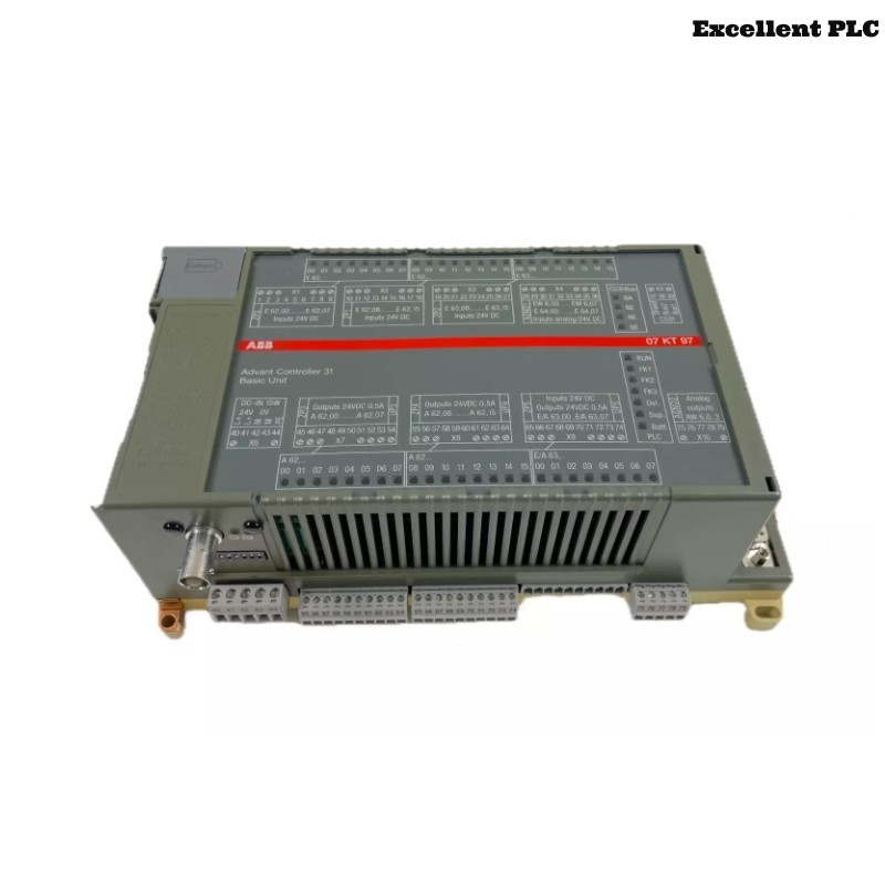
The ABB 07KT94 GJR5252100R0101 PLC Controller serves as the main processing unit in Procontic automation systems. It executes control logic, manages I/O communication, and ensures system synchronization in industrial environments.
This Installation Guide covers practical Setup, wiring, and Commissioning procedures for reliable operation.
System Role
- Central PLC Controller for process execution
- Maintains communication with local and remote I/O modules
- Ensures System Configuration integrity
- Interfaces with engineering workstations and supervisory systems
Environment Check
Before installing, validate the following:
- Power supply meets voltage and current requirements
- Control cabinet is properly grounded
- Ambient temperature is within specified range
- Slot allocation matches System Configuration
- Latest project configuration is available for download
Rack Integration
- Align module rails carefully before insertion
- Insert halfway, confirm backplane alignment
- Apply uniform pressure to fully seat module
- Lock side clips securely
Incorrect seating may cause communication issues during runtime.
Wiring & Connections
- Connect power terminals observing polarity
- Route communication cables separately from power lines
- Terminate shields properly to avoid loops
- Check signal references and grounding
Commissioning Sequence
Field engineers typically follow this logical order rather than rigid steps:
- Power up with minimum modules connected
- Verify PLC enters stable idle state
- Load System Configuration from engineering workstation
- Enable communication interfaces incrementally
- Add I/O modules one at a time, monitoring status
BOOT_CPU
CHECK_BASE_STATE
IMPORT_CONFIG
ENABLE_BUS
ADD_MODULE_STEPWISE
MONITOR_STATUS
Operational Validation
- Cycle power to confirm restart stability
- Simulate I/O signals for all channels
- Monitor diagnostic buffer for warnings
- Observe system behavior for 20–30 minutes
Successful validation ensures the controller is ready for continuous industrial operation.