

Guide Map
- Device Role
- Installation Conditions
- Mounting Method
- Connection Strategy
- Startup Logic
- Performance Check
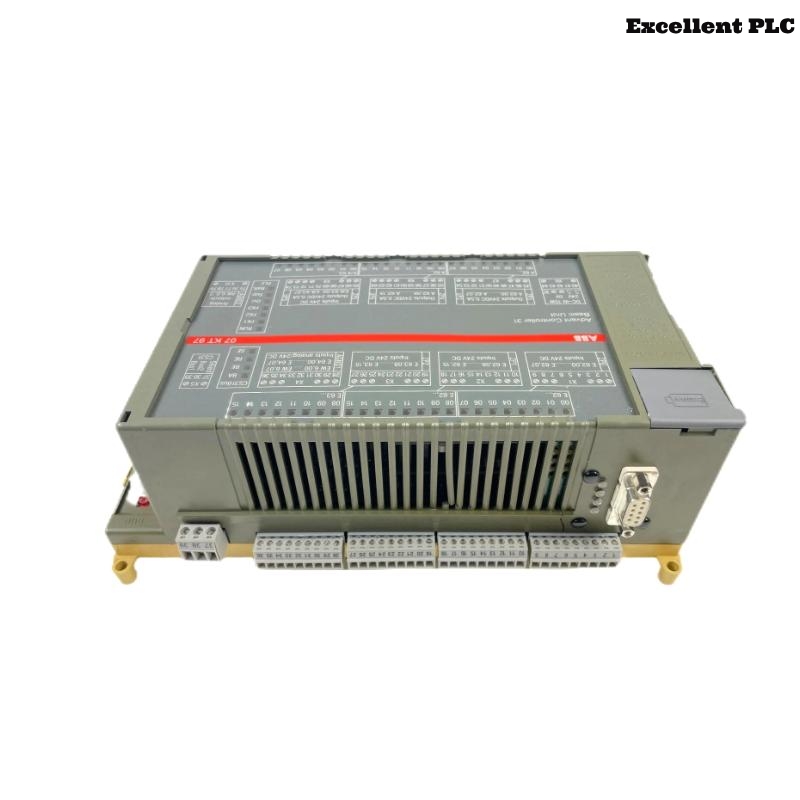
Device Role
The ABB 07KT97D GJR5253000R0272/GJR5253000R0276 PLC Controller is used in Procontic automation systems as a central control unit responsible for logic execution, communication handling, and coordination of distributed I/O modules.
This Installation Guide emphasizes practical Setup and Commissioning behavior observed in real industrial environments.
Installation Conditions
Before installation, the surrounding system must be evaluated:
- Stable 24V DC supply without ripple or transient spikes
- Proper cabinet grounding and bonding between panels
- Adequate spacing between control and power devices
- Verified System Configuration matching physical layout
Unstable conditions at this stage often lead to hidden Troubleshooting issues later.
Mounting Method
Mounting should focus on connector integrity rather than speed:
- Align module carefully with rack guide rails
- Insert slowly until resistance is felt
- Check connector alignment before final push
- Lock module firmly into position
Improper insertion can cause intermittent backplane contact, leading to communication faults.
Connection Strategy
Signal stability depends on wiring discipline:
- Separate communication cables from high-current lines
- Use shielded cables for all critical signals
- Ensure single-point grounding for shields
- Verify all terminal connections are secure
This reduces noise-related Fault Diagnosis complexity.
Startup Logic
Instead of powering everything at once, use a controlled startup sequence:
- Power the PLC Controller independently first
- Confirm stable CPU state before enabling I/O
- Load System Configuration only after stable initialization
- Gradually activate communication interfaces
POWER_BASE_UNIT
CHECK_CPU_STATUS
LOAD_CONFIGURATION
ENABLE_COMMUNICATION
EXPAND_SYSTEM
This logic minimizes risk during initial Commissioning.
Performance Check
Final validation should simulate real conditions:
- Run system under expected load conditions
- Monitor communication stability across all modules
- Check diagnostic logs for hidden warnings
- Perform restart test to verify boot reliability
Successful checks confirm the PLC Controller is ready for continuous operation.