

Guide Navigation
- Device Overview
- Application Role
- Installation Planning
- Cabinet Preparation
- Mounting Process
- Power Connection
- Communication Wiring
- System Loading
- Commissioning Approach
- Stress Test
- Deployment Checklist
Device Overview
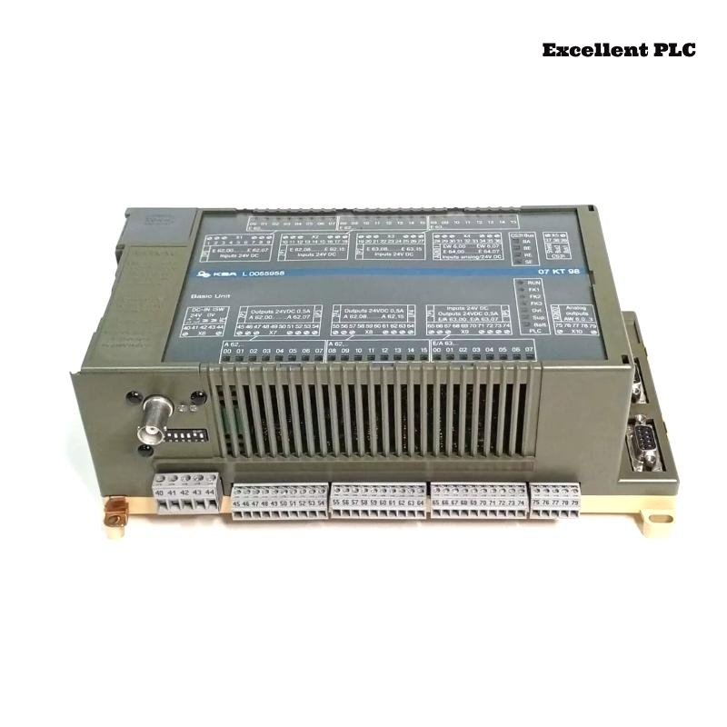
The ABB 07KT98C GJR5253100R3260 PLC Controller is a central automation processor used in Procontic systems. It executes real-time control logic, manages communication buses, and coordinates distributed I/O modules in complex industrial environments.
This Installation Guide provides structured Setup and Commissioning instructions based on practical field engineering experience.
Application Role
- Acts as the primary PLC Controller for process execution
- Manages communication between I/O modules and supervisory systems
- Maintains System Configuration integrity
- Ensures deterministic system response
Installation Planning
Before installation, careful planning is required:
- Review System Configuration and module layout
- Identify cable routing paths
- Allocate cabinet space for airflow
- Prepare backup configuration files
Cabinet Preparation
- Verify grounding resistance and bonding
- Check for potential EMI sources
- Ensure proper ventilation and cooling
- Confirm separation between power and signal areas
Good preparation reduces future Troubleshooting efforts.
Mounting Process
Follow a controlled insertion technique:
- Align the module with rack guides precisely
- Insert partially to confirm connector alignment
- Apply even pressure to fully seat the module
- Secure mechanical locks firmly
Incorrect mounting can lead to intermittent communication faults.
Power Connection
- Connect DC supply with correct polarity
- Measure voltage stability before startup
- Ensure tight terminal connections
- Use filtered power sources where necessary
Communication Wiring
- Use shielded cables for all communication lines
- Separate signal wiring from high-current cables
- Ground shielding at one reference point
- Maintain consistent routing paths
These practices simplify Fault Diagnosis later.
System Loading
- Connect engineering workstation
- Load verified System Configuration
- Check module addressing and mapping
- Verify communication parameters
Commissioning Approach
Adopt a phased commissioning strategy:
- Power PLC Controller independently
- Verify CPU status indicators
- Enable communication interfaces step by step
- Add I/O modules incrementally
- Monitor diagnostics continuously
START_CONTROLLER
VERIFY_CPU_STATE
LOAD_PROJECT
ENABLE_NETWORK
ADD_MODULES_STEPWISE
CHECK_DIAGNOSTICS
Stress Test
- Run system under peak load conditions
- Monitor communication stability
- Check for delayed responses
- Review diagnostic logs for hidden faults
Deployment Checklist
- All modules detected and operational
- No active faults in system diagnostics
- Stable communication under load
- Reliable restart performance
Completion of this checklist confirms successful installation and readiness.