

Navigation
- Technical Background
- Project Context
- Pre-Installation Strategy
- Rack Integration
- Wiring Details
- Setup & Commissioning Sequence
- Field Validation
- Engineer Notes
Technical Background
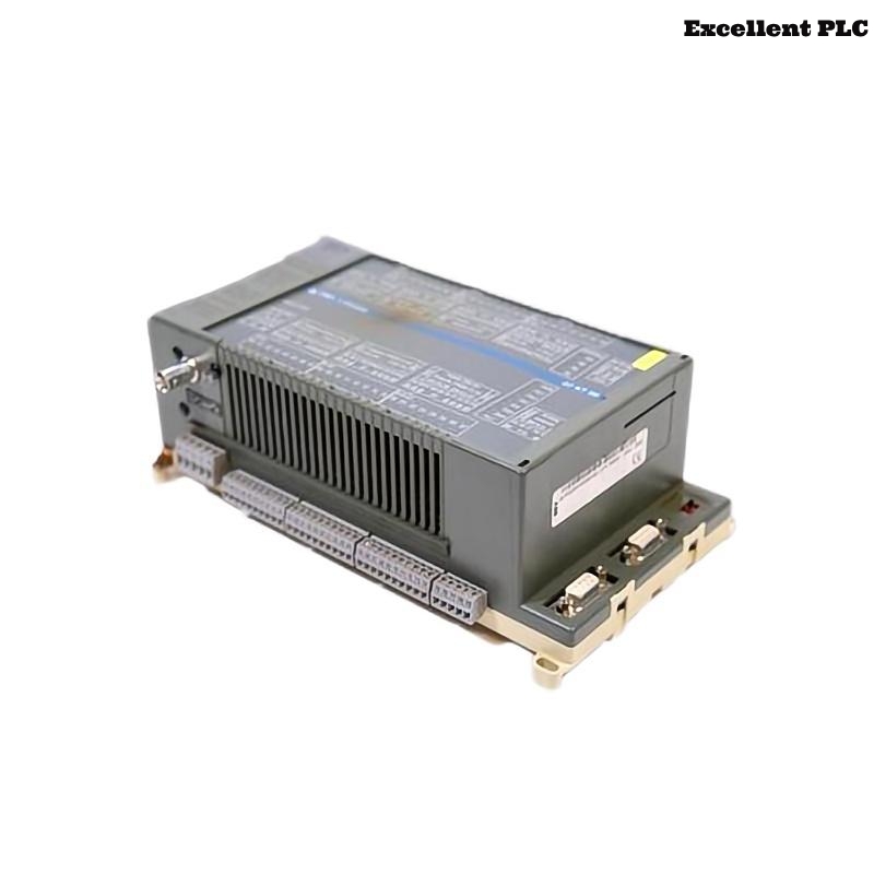
The ABB 07KT98E2 / 07KT98F GJR5253100R0160 PLC Controller is widely used in Procontic automation systems for executing control logic, handling communication buses, and maintaining stable System Configuration across distributed I/O modules.
This Installation Guide is based on real Setup and Commissioning experience in industrial environments, where improper installation often leads to hidden Troubleshooting issues later.
Project Context
In one recent commissioning project, this PLC Controller was installed in a multi-rack system controlling a conveyor line. The system initially powered up correctly, but instability appeared after expansion, highlighting the importance of proper installation strategy.
- System included 20+ I/O modules
- Mixed digital and analog signals
- Long communication cable runs (>25m)
Pre-Installation Strategy
Instead of jumping directly into installation, the following checks were performed:
- Measured cabinet grounding resistance (< 1Ω target)
- Verified 24V DC supply ripple (< 100mV)
- Checked layout against System Configuration file
- Identified potential EMI sources near inverter drives
These steps significantly reduced later Fault Diagnosis complexity.
Rack Integration
During installation, attention was given to connector alignment:
- Module inserted halfway to verify backplane alignment
- Visual check performed before full insertion
- Final seating applied with even pressure
In a previous case, improper insertion caused intermittent bus faults that only appeared during vibration.
Wiring Details
Signal wiring followed strict separation rules:
- Communication cables routed separately from motor power lines
- Shielded twisted-pair used for bus communication
- Shield grounded at cabinet entry point only
This wiring approach minimizes future Troubleshooting related to noise.
Setup & Commissioning Sequence
Instead of full system startup, a staged Commissioning method was used:
- Power only the PLC Controller first
- Confirm CPU stable RUN/IDLE state
- Download System Configuration
- Enable communication bus without I/O load
- Add I/O modules incrementally
POWER_ON_CPU
VERIFY_STATUS
DOWNLOAD_CONFIG
ENABLE_BUS
ADD_IO_STEPWISE
CHECK_DIAGNOSTICS
This approach makes Troubleshooting much easier if issues appear.
Field Validation
After Commissioning, real operation tests were performed:
- Continuous run for 2 hours under load
- Monitoring communication error counters
- Simulating signal spikes on analog channels
No communication faults were detected after proper Setup.
Engineer Notes
From field experience, most Installation Guide failures are not due to the PLC Controller itself, but due to:
- Improper grounding
- Poor cable routing
- Skipping staged Commissioning
Following a structured Setup and Commissioning process ensures long-term stability.