

Contents
- Overview & Key Features
- System Role in Automation
- Pre-Installation Preparation
- Mounting & Rack Integration
- Wiring Best Practices & EMI Mitigation
- Startup & Commissioning Procedure
- Field Testing & Validation
- Practical Engineer Tips
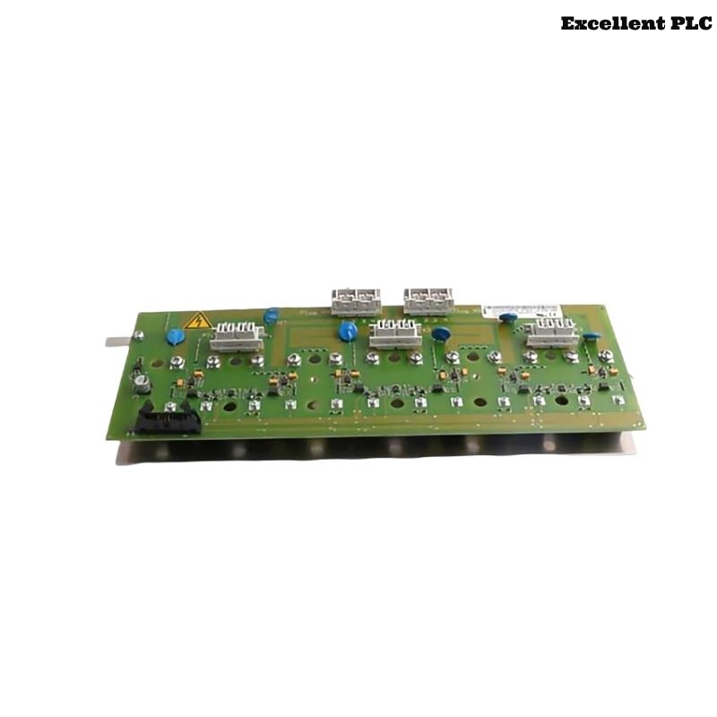
ABB 07SS91 PLC Controller Overview & Key Features
The ABB 07SS91 PLC Controller is designed for reliable operation in Procontic automation systems, providing precise I/O control, communication management, and system configuration. Correct Setup and Commissioning significantly reduce the risk of future faults.
Similar guidelines also apply to variants of this model used in industrial lines requiring distributed I/O and high system reliability.
Role of ABB 07SS91 in Automation Systems
- Executes sequential control logic for processes
- Coordinates analog and digital I/O modules
- Maintains deterministic timing for complex operations
- Provides diagnostics for fault detection and monitoring
Pre-Installation Preparation
- Measure cabinet grounding resistance (< 1Ω)
- Check 24V DC supply stability (±0.1V)
- Identify potential EMI sources in cabinet and nearby equipment
- Confirm rack layout matches System Configuration plan
Field cases show skipping these checks is the most common cause of intermittent communication faults.
ABB 07SS91 PLC Mounting & Rack Integration
Recommended field method:
- Align module with backplane and insert partially
- Verify connector alignment and absence of mechanical obstruction
- Fully seat module with steady pressure
- Lock mechanical clips and ensure vibration stability
Incorrect seating has been observed to cause communication instability during machine operation.
Wiring Best Practices & EMI Mitigation
- Route communication cables away from high-power lines
- Use shielded twisted-pair wiring for bus communication
- Ground shields at a single reference point in cabinet
- Keep cable lengths minimal and avoid loops near inverters
Startup & Commissioning Procedure
- Power only the ABB 07SS91 PLC Controller initially
- Verify CPU RUN/IDLE status LEDs
- Load verified System Configuration
- Enable communication bus with no I/O load
- Add I/O modules incrementally while monitoring diagnostics
POWER_ON_CPU
VERIFY_STATUS
LOAD_SYSTEM_CONFIG
ENABLE_BUS
ADD_IO_STEPWISE
MONITOR_DIAGNOSTICS
Field Testing & Validation
- Run full system under operational load for 2–3 hours
- Monitor CPU and communication error counters
- Simulate analog/digital input disturbances to validate response
- Confirm consistent system operation for production
Practical Engineer Tips
Most installation issues come from improper grounding, skipped pre-checks, or cable routing near high-power lines. Following this guide ensures stable PLC operation and minimizes future Troubleshooting.