

Navigation
- Fault Overview
- Fault Symptoms
- Diagnostic Thinking
- Root Cause Analysis
- Real Case
- Repair Solution
- Prevention
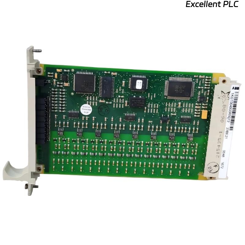
ABB 23BE21 PLC Module Fault Troubleshooting Overview
ABB 23BE21 PLC module faults are usually caused by signal mismatch or wiring errors rather than module failure. This Troubleshooting guide focuses on how to perform efficient Fault Diagnosis using engineering logic.
ABB 23BE21 Fault Symptoms
- Input values inconsistent with actual field signals
- Outputs fail to trigger actuators
- System behaves incorrectly despite correct PLC logic
- Intermittent signal loss
ABB PLC Fault Diagnosis Thinking Process
Instead of replacing the module immediately, experienced engineers follow this logic:
- Is the signal correct at the source?
- Does the signal reach the module?
- Is the module processing correctly?
- Is configuration aligned with wiring?
This approach avoids unnecessary hardware replacement.
Common Causes of ABB 23BE21 Fault
- Wrong wiring of input/output channels
- Incorrect module configuration
- Signal interference from nearby equipment
- Loose or oxidized terminals
Real Case: ABB 23BE21 Troubleshooting
During commissioning of a packaging system, sensors showed correct signals, but PLC readings were incorrect.
- Field signal: OK
- PLC logic: OK
- Module input: incorrect values
Investigation revealed that signal wires were connected to wrong terminals due to similar labeling.
ABB 23BE21 Repair Solution
- Rewire according to correct terminal mapping
- Verify signal path from sensor to module
- Secure all connections
- Re-run system test
After correction, all signals matched expected values and system operated normally.
Preventing ABB 23BE21 PLC Module Faults
- Follow Installation Guide during Setup
- Label all wiring clearly
- Verify I/O mapping before startup
- Perform signal simulation during commissioning
Proper Fault Diagnosis and careful Setup greatly reduce troubleshooting time and improve reliability of ABB 23BE21 PLC modules.