

Table of Contents
- Installation Overview
- Gap Setting and Mounting
- Wiring and Signal Setup
- Calibration and System Configuration
- Commissioning Validation
- Installation FAQ
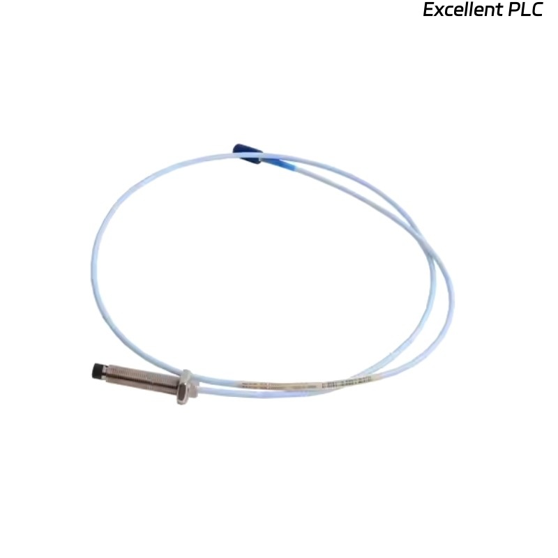
Bently Nevada 102045-080-00-05 Installation Overview
This guide explains the proper installation of the Bently Nevada 102045-080-00-05 proximity probe, covering gap adjustment, mounting alignment, and calibration for precise shaft vibration measurement.
Field experience shows that incorrect Setup is the leading cause of inaccurate vibration readings. Following this Installation Guide minimizes signal errors and ensures reliable long-term operation.
Gap Setting and Mounting
- Recommended probe gap: 0.5 mm – 1.5 mm
- Maintain perpendicular alignment to shaft surface
- Install away from shaft defects or keyways
In a steam turbine project, a 2.0 mm gap caused ±90 μm signal fluctuation. After adjusting to 1.0 mm and aligning the probe correctly, readings stabilized to ±12 μm.
Wiring and Signal Setup
- Use original extension cables for impedance matching
- Maintain separation from high-power equipment to prevent EMI
- Implement single-point grounding
# Signal verification steps
MEASURE OUTPUT VOLTAGE
CHECK NOISE LEVEL
VERIFY CABLE INTEGRITY
Calibration and System Configuration
- Set probe sensitivity (e.g., 7.87 mV/μm)
- Perform zero calibration
- Verify linear measurement range
One commissioning case showed displayed values doubled due to incorrect scaling. Recalibration corrected the signal immediately.
Commissioning Validation
- Check signal stability across operating speeds
- Confirm consistent waveform output
- Ensure no abnormal noise spikes
Improper grounding in one field installation caused ±20 μm ripple, which reduced to ±5 μm after correction.
Installation FAQ
What is the correct gap for Bently Nevada 102045-080-00-05?
The recommended gap is 0.5 mm – 1.5 mm. Always verify using calibration curves for linear operation.
Why is probe alignment important?
Misalignment alters the electromagnetic interaction with the shaft, causing unstable or non-linear readings.
Does cable routing affect signal stability?
Yes. Proximity probe cables routed near high-power equipment may pick up EMI noise, resulting in signal fluctuation.
Is calibration required during commissioning?
Yes. Calibration ensures displacement readings accurately reflect actual shaft movement.