

Table of Contents
- Bently Nevada 106765-25 Accelerometer Installation Overview
- Installation Environment Considerations for 106765-25
- Pre-Installation Checks and Setup Planning
- Bently Nevada 106765-25 Mounting and Mechanical Coupling
- Signal Wiring and Grounding Strategy
- System Configuration and Integration Setup
- Commissioning Workflow and Signal Validation
- Real Field Installation Case
- Bently Nevada 106765-25 Installation FAQ
- Final Notes on Installation
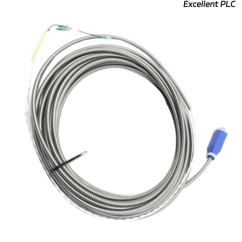
Bently Nevada 106765-25 Accelerometer Installation Overview
Bently Nevada 106765-25 accelerometer installation problems are typically caused by poor mechanical coupling and incorrect cable routing, not sensor defects. In high-vibration environments, improper installation can amplify readings by 2–3 times, leading to false alarms during commissioning.
Installation Environment Considerations for 106765-25
Before Setup, evaluate the installation environment:
- Presence of high-frequency drives (VFDs)
- Temperature range and thermal expansion impact
- Structural rigidity of mounting location
Field experience shows that flexible mounting structures can introduce low-frequency vibration distortion above 4 mm/s.
Pre-Installation Checks and Setup Planning
- Verify sensor sensitivity and calibration data
- Inspect mounting surface roughness (Ra < 3.2 μm recommended)
- Confirm cable shielding specification (>85% coverage)
- Ensure correct interface with PLC Controller or monitoring module
Bently Nevada 106765-25 Mounting and Mechanical Coupling
Mechanical coupling quality is the most critical factor:
- Use stud mounting for permanent installations
- Apply torque between 6–8 Nm
- Remove paint and oxidation layer before mounting
  // Mechanical Integrity Check
  Measure Idle Vibration
  IF RMS > 2 mm/s THEN
     Check Mounting Surface;
  END_IF;
Loose mounting often introduces resonance peaks misinterpreted as bearing faults.
Signal Wiring and Grounding Strategy
- Use twisted-pair shielded cables
- Ground shield at control cabinet only
- Maintain separation from power cables (>300 mm)
In one plant, improper grounding created ±2.8 mm/s signal fluctuation due to ground loop currents.
System Configuration and Integration Setup
During Setup, correct system configuration is essential:
- Match signal type (4–20 mA or voltage)
- Configure scaling (e.g., 0–50 mm/s)
- Set alarm thresholds based on machine standards
Incorrect scaling frequently leads to false trip conditions in PLC or DCS systems.
Commissioning Workflow and Signal Validation
- Verify baseline vibration (<1 mm/s typical for idle)
- Cross-check with handheld vibration analyzer
- Monitor signal stability over 1 hour
Stable signals should not drift more than ±0.5 mm/s under steady operation.
Real Field Installation Case
In a petrochemical pump system, vibration readings reached 10 mm/s immediately after installation.
Investigation showed:
- Mounting surface covered with paint
- Signal cable routed alongside motor power cable
After surface cleaning and cable rerouting, vibration dropped to 2.2 mm/s, matching portable analyzer results.
Bently Nevada 106765-25 Installation FAQ
Why does the Bently Nevada 106765-25 show higher vibration than expected?
This is usually due to poor mounting or signal interference. Verify mechanical coupling and compare readings with a reference analyzer.
Is grounding really important for accelerometer installation?
Yes. Improper grounding can introduce noise and cause unstable readings, especially in high EMI environments.
What is the most common installation mistake?
Installing the sensor on painted or uneven surfaces, which reduces mechanical coupling and distorts vibration measurements.
Final Notes on Installation
The Bently Nevada 106765-25 accelerometer requires precise installation practices to ensure reliable vibration monitoring. Mechanical mounting quality, proper wiring, and structured commissioning are the key factors for long-term system stability.