

Table of Contents
- Bently Nevada 130539-12 Sensor Overview
- Application Areas of 130539-12
- Pre-Installation Preparations
- Mechanical Mounting and Alignment
- Cable Routing and Shielding
- System Configuration and Setup
- Commissioning and Signal Verification
- Field Installation Case Study
- Installation FAQ
- Final Engineering Notes
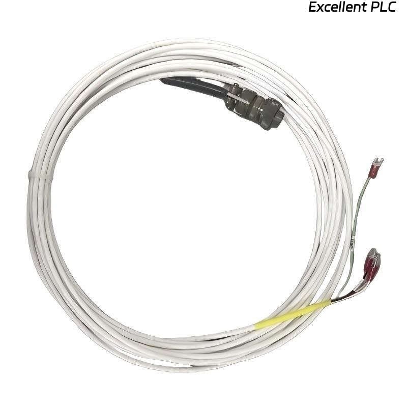
Bently Nevada 130539-12 Sensor Overview
The Bently Nevada 130539-12 proximity probe is designed for precise vibration and shaft displacement monitoring in industrial machinery. Proper installation ensures reliable performance and accurate data for predictive maintenance and machinery protection.
Common issues during installation include probe misalignment and improper wiring, which can lead to inaccurate readings and faulty system behavior.
Application Areas of 130539-12
- Steam turbines, gas turbines, and compressors
- Pumps, motors, and high-speed rotating equipment
- Critical machinery where condition monitoring is essential for safety and reliability
- Integration with Bently Nevada 3500 series vibration monitoring systems
Pre-Installation Preparations
- Check the calibration certificate and model number of the sensor
- Inspect the probe for physical damage, particularly on the tip and cable
- Ensure mounting surfaces are clean, rigid, and free of any debris
- Prepare the necessary tools and equipment, including feeler gauges and torque wrenches
Mechanical Mounting and Alignment
- Ensure the probe is aligned perpendicularly to the shaft’s surface
- Mount the probe with sufficient clearance, typically 0.010–0.020 inches, between the probe tip and the shaft
- Use a torque wrench to secure the probe mount to the required specifications
- Use a feeler gauge or alignment tool to verify correct gap and probe positioning
  // Alignment Check Logic
  IF Probe_Alignment NOT_CORRECT THEN
      Re-align_Probe;
  ELSE IF Gap_Out_Of_Spec THEN
      Adjust_Gap;
  END_IF;
Cable Routing and Shielding
- Use shielded cables to maintain signal integrity and reduce noise interference
- Route cables away from power lines, motors, and other high-current equipment
- Ground the shield at one end only, typically at the monitoring system side
- Ensure cables are securely fastened and avoid excessive bends or torsion
System Configuration and Setup
- Verify the probe type and correct scaling factor in the Bently Nevada 3500 system
- Configure the alarm thresholds and operating limits based on machinery specifications
- Check the system settings for accurate data logging, filtering, and monitoring parameters
- Ensure the correct channel assignments for the sensor in the monitoring module
Commissioning and Signal Verification
- Power on the system and allow the sensor to stabilize
- Verify the baseline voltage (typically between -8V and -10V)
- Check for smooth variation in the signal as the shaft rotates
- Perform a comparison with a portable vibration analyzer to ensure accurate readings
- Record and validate initial data to confirm sensor functionality
Field Installation Case Study
A high-speed compressor installation was experiencing fluctuating readings from the 130539-12 proximity probe. Upon investigation, the following was found:
- The probe was misaligned, causing the signal to fluctuate unpredictably
- The cable was routed too close to a power line, introducing electromagnetic interference (EMI)
After realigning the probe and rerouting the cable away from the power line, the readings stabilized and matched the expected values within ±0.05 mil.
Installation FAQ
Why are the vibration readings unstable during installation?
Unstable readings often result from mechanical misalignment, incorrect gap settings, or EMI from nearby power lines.
How can I verify the probe gap?
The correct gap can be verified using feeler gauges or system software. Refer to the manufacturer’s specifications for the required gap range.
Can the sensor be installed in high-temperature environments?
Yes, but make sure to check the sensor’s temperature rating and ensure the cable insulation can withstand the temperature range.
Final Engineering Notes
The Bently Nevada 130539-12 installation is straightforward, but careful attention to detail in mechanical alignment, proper cable routing, and system configuration ensures accurate vibration data for effective machinery protection.