

Table of Contents
- 130539-12 Fault Entry Point
- Signal Fault Patterns in 130539-12
- Engineering Fault Diagnosis Thinking Process
- Common Causes of 130539-12 Fault
- On-site Diagnostic Verification Methods
- Corrective Actions and Repair Strategy
- Real Fault Investigation Case
- Troubleshooting FAQ
- Final Technical Summary
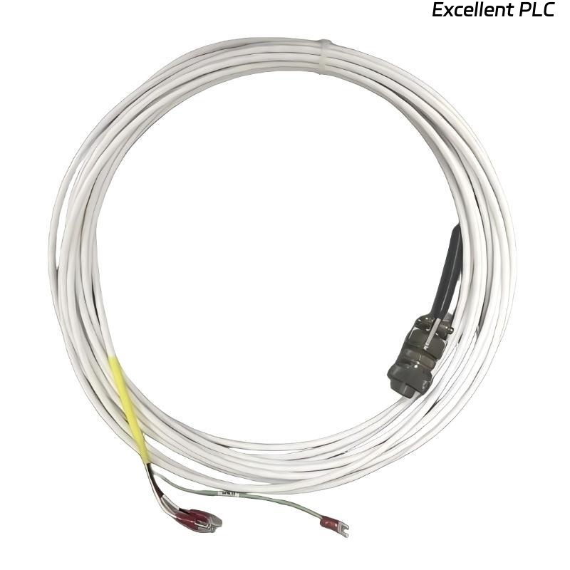
130539-12 Fault Entry Point
Bently Nevada 130539-12 proximity probe faults usually present as unstable signals or false alarms, but in over 80% of field cases, the root cause is not probe failure. Instead, issues originate from installation conditions, EMI interference, or incorrect system configuration.
Signal Fault Patterns in 130539-12
- Output voltage fluctuating between -6V and -12V
- Sudden spikes during motor or inverter startup
- Flatline signal (no response to shaft movement)
- Gradual signal drift during long operation
Engineering Fault Diagnosis Thinking Process
Instead of replacing the sensor directly, experienced engineers isolate faults using a layered approach:
- First isolate electrical issues (power, cable, grounding)
- Then evaluate mechanical factors (gap, alignment)
- Finally validate system configuration (scale, channel, alarm)
  // Fault Thinking Logic (Field Practice)
  IF Signal_Spike DURING Motor_Start THEN
      Suspect_EMI;
  ELSE IF Signal_Flat THEN
      Check_Probe_Gap;
  ELSE IF Drift_Observed THEN
      Check_Temperature_Or_Cable;
  END_IF;
Common Causes of 130539-12 Fault
- Electromagnetic interference from VFD or high-current cables
- Improper shielding or dual grounding
- Incorrect probe gap (outside linear range)
- Loose connector or degraded cable insulation
On-site Diagnostic Verification Methods
- Measure DC voltage output using a calibrated multimeter
- Use oscilloscope to detect waveform distortion or noise
- Compare with redundant probe or portable vibration analyzer
- Physically inspect probe mounting and bracket rigidity
Corrective Actions and Repair Strategy
- Re-route signal cable away from power sources
- Apply single-point grounding for shield
- Adjust probe gap to restore linear voltage range
- Secure connectors and replace damaged cables if needed
Real Fault Investigation Case
In a turbine protection system, a 130539-12 probe triggered high vibration alarms intermittently. Field observations:
- Noise spikes appeared only during inverter startup
- Voltage fluctuated rapidly from -7V to -11V
Engineers initially suspected probe failure. However, further diagnosis revealed cable routing parallel to a 400V motor line. After rerouting and correcting grounding, noise disappeared and vibration stabilized from 9 mm/s to 3.2 mm/s RMS.
Troubleshooting FAQ
Why does the probe show spikes only during startup?
This is a typical EMI issue caused by nearby high-frequency drives or motor cables.
Is replacing the probe the first solution?
No. Always eliminate installation and interference factors before replacing hardware.
What indicates a gap-related fault?
If voltage is outside normal range and does not respond to shaft movement, the gap is likely incorrect.
Final Technical Summary
The Bently Nevada 130539-12 Troubleshooting Guide highlights that effective fault diagnosis relies on structured thinking and field validation. Most issues are external and can be resolved through proper wiring, grounding, and mechanical correction rather than sensor replacement.