

Table of Contents
- Bently Nevada 130938-07-10-01-00 Sensor Installation Context
- Engineering Strategy Before Sensor Installation
- Mechanical Installation of 130938-07-10-01-00 Vibration Probe
- Electrical Wiring and System Configuration
- Setup and Commissioning Behavior Validation
- Installation Optimization in Harsh Environments
- FAQ
- Technical Summary
Bently Nevada 130938-07-10-01-00 Sensor Installation Context
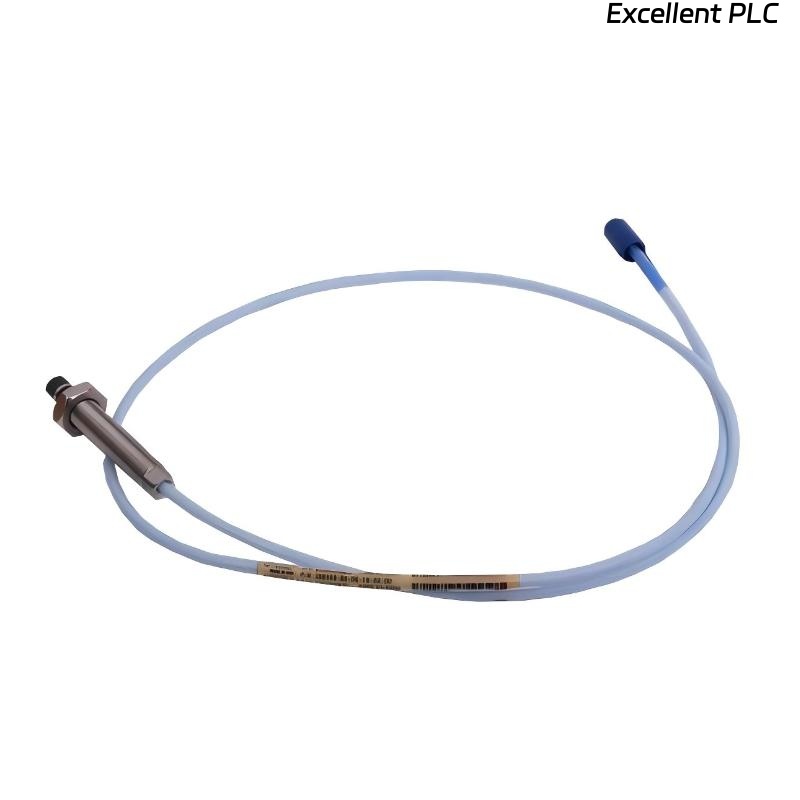
Bently Nevada 130938-07-10-01-00 vibration probe installation directly affects signal linearity. In field applications, abnormal readings are often caused by improper probe positioning rather than sensor defects.
This Installation Guide focuses on practical setup, wiring, and commissioning for stable integration into PLC and monitoring module systems.
Engineering Strategy Before Sensor Installation
Before installation, engineers should define measurement objectives and system configuration.
- Determine shaft measurement location (radial or axial)
- Confirm target material conductivity
- Ensure compatibility with extension cable and proximitor
- Evaluate environmental conditions (temperature, oil, vibration)
Field Observation: In one compressor system, incorrect target material resulted in low sensitivity signal response.
Mechanical Installation of 130938-07-10-01-00 Vibration Probe
Mechanical stability is critical for accurate vibration monitoring.
- Install probe perpendicular to shaft surface
- Use calibrated torque to secure mounting thread
- Maintain recommended probe gap (typically around 1 mm)
- Avoid mounting on flexible brackets
Improper alignment introduces nonlinear signal errors, especially at high rotational speeds.
Electrical Wiring and System Configuration
Correct wiring ensures signal integrity during operation.
- Connect probe → extension cable → proximitor → monitoring module
- Ensure shield grounding at one end only
- Separate signal cables from high-voltage lines
- Verify power supply stability (-24VDC typical)
Noise interference is a common issue in PLC-based systems when grounding is incorrect.
Setup and Commissioning Behavior Validation
Commissioning should validate sensor output under actual machine conditions.
- Measure initial DC gap voltage (e.g., -8V to -12V typical)
- Observe signal response during startup and shutdown
- Compare with baseline vibration data
Real Case:
During pump commissioning, signal fluctuation of ±2 mm/s was observed. After re-routing cable away from inverter lines, fluctuation reduced to ±0.5 mm/s.
Installation Optimization in Harsh Environments
- Use protective conduit for oil-contaminated environments
- Apply anti-vibration mounting structures
- Perform periodic probe gap verification
- Document all setup parameters for troubleshooting
FAQ
Why is the sensor output unstable after installation?
This is usually due to electromagnetic interference or improper probe alignment.
What is the correct wiring sequence?
The sensor must be connected through extension cable and proximitor before reaching PLC or monitoring module.
Can this sensor be used in high-temperature environments?
Yes, but installation must consider temperature rating and proper cable protection.
Technical Summary
This Installation Guide demonstrates that successful deployment of the Bently Nevada 130938-07-10-01-00 vibration probe depends on mechanical precision, correct wiring strategy, and systematic commissioning validation. Proper installation ensures reliable data for vibration monitoring and fault diagnosis.