

Table of Contents
- 130938-10-10-01 Installation Overview
- Role of 130938-10-10-01 Proximity Probe
- Critical Installation Risks to Avoid
- Mechanical Mounting & Gap Setup
- Wiring and Signal Integrity Setup
- System Configuration and Setup
- Commissioning and Signal Calibration
- Field Commissioning Case
- Installation FAQ
- Final Engineering Summary
130938-10-10-01 Installation Overview
Bently Nevada 130938-10-10-01 proximity probe installation errors are one of the main causes of false vibration alarms. In most commissioning projects, incorrect probe gap and poor grounding—not hardware defects—lead to unstable readings.
This Installation Guide focuses on practical setup, mechanical alignment, and commissioning validation to ensure accurate shaft displacement monitoring.
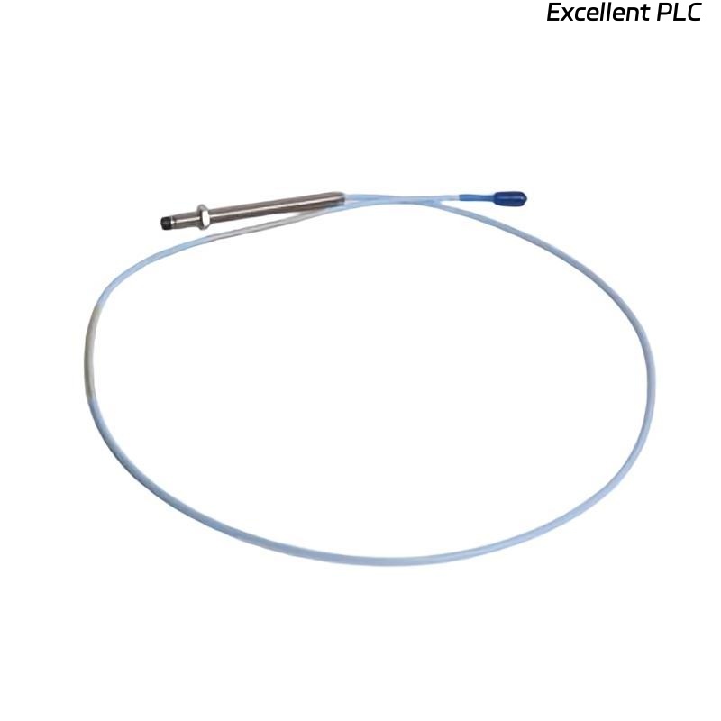
Role of 130938-10-10-01 Proximity Probe
- Measures shaft displacement using eddy current principle
- Provides continuous vibration and position feedback
- Interfaces with Bently Nevada monitoring systems (e.g., 3500)
- Critical for turbine, compressor, and motor protection
Critical Installation Risks to Avoid
- Incorrect probe gap (outside linear measurement range)
- Probe misalignment with shaft surface
- Improper grounding causing signal noise
- Cable routed near high-voltage equipment
Mechanical Mounting & Gap Setup
Proper gap setting is the foundation of accurate measurement.
- Adjust probe gap to achieve ~-10V DC output (typical reference)
- Ensure probe tip is perpendicular to shaft surface
- Use rigid mounting bracket to prevent vibration-induced movement
- Verify clearance during shaft rotation
  // Gap Adjustment Logic
  Measure Voltage:
  IF Voltage > -8V THEN
      Increase Gap;
  ELSE IF Voltage < -12V THEN
      Decrease Gap;
  END_IF;
Wiring and Signal Integrity Setup
- Use shielded cable (e.g., 130539 series)
- Ground shielding at monitor side only
- Avoid routing near VFD or motor cables
- Secure connectors to prevent intermittent signals
System Configuration and Setup
- Configure channel type as proximity probe in monitoring system
- Set correct scale factor (mV/μm or mV/mil)
- Define alarm thresholds based on machine limits
- Verify signal mapping to PLC or control system
Commissioning and Signal Calibration
- Measure static voltage (baseline check)
- Start machine at low speed and monitor signal trend
- Compare readings with reference instrument
- Confirm stable waveform under full load
Field Commissioning Case
During commissioning of a steam turbine, the 130938-10-10-01 probe showed unstable readings:
- Voltage fluctuated between -8V and -11V
- Vibration readings inconsistent with mechanical condition
Engineers initially suspected probe failure. After rechecking:
- Probe angle was slightly misaligned
- Mounting bracket had minor looseness
After correction:
- Voltage stabilized at -10.2V
- Vibration reading aligned with expected 3.5 mm/s
Installation FAQ
What is the ideal voltage for probe setup?
Typically around -10V DC, ensuring operation within the linear range.
Can mechanical misalignment affect readings?
Yes, even small angular deviations can cause signal distortion.
Is shielding always required?
Yes, proper shielding is critical to avoid EMI interference in industrial environments.
Final Engineering Summary
The Bently Nevada 130938-10-10-01 Installation Guide highlights that precision in mechanical setup, correct wiring, and systematic commissioning are essential. Reliable measurement depends more on installation discipline than component replacement.