

Table of Contents
- Bently Nevada 133811-01 Temperature Monitor Troubleshooting Entry
- Temperature Signal Fault Behavior Patterns
- Structured Fault Diagnosis Process
- Common Causes of Temperature Monitoring Fault
- Field Case: False High Temperature Alarm
- Repair and System Recovery Actions
- FAQ
- Technical Summary
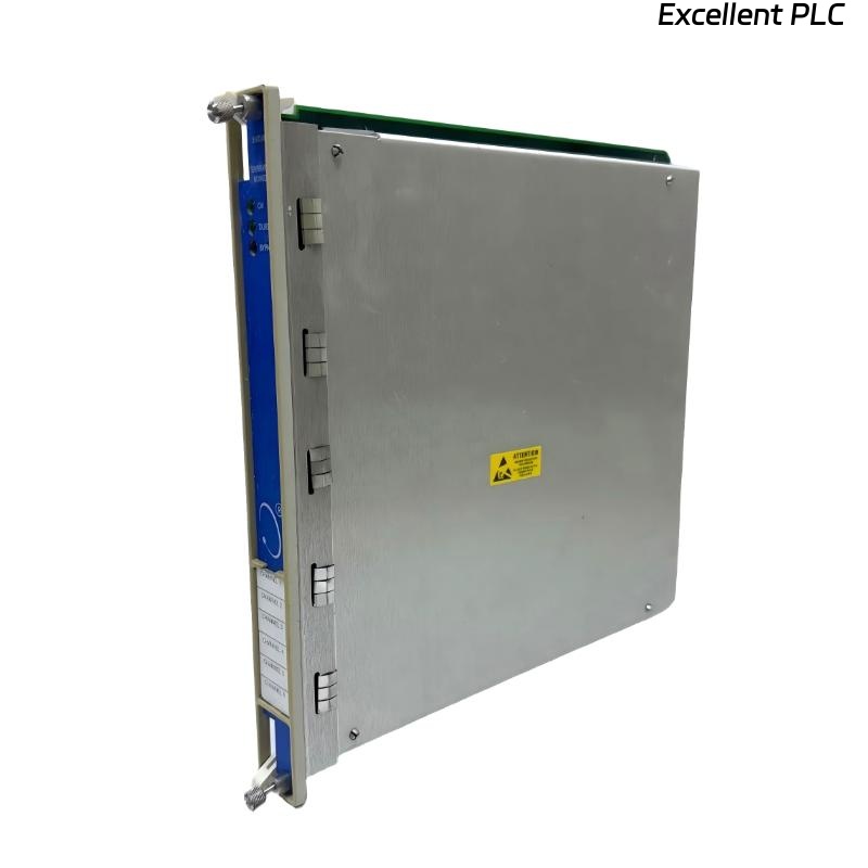
Bently Nevada 133811-01 Temperature Monitor Troubleshooting Entry
Bently Nevada 133811-01 temperature monitor module troubleshooting typically shows that abnormal temperature alarms are caused by signal chain issues rather than actual thermal conditions.
This guide provides a fault diagnosis methodology based on signal behavior and engineering logic.
Temperature Signal Fault Behavior Patterns
- Gradual drift without process change
- Sudden spikes triggering alarms
- Flatline readings (no variation)
- Channel-to-channel inconsistency
Each pattern indicates a different fault category.
Structured Fault Diagnosis Process
IF gradual drift:
    check sensor aging
    verify calibration

IF sudden spike:
    inspect wiring integrity
    check EMI exposure

IF flatline signal:
    test sensor continuity
    verify module input

IF inconsistent channels:
    compare configuration
    check wiring mapping
This troubleshooting logic aligns with real field diagnostics.
Common Causes of Temperature Monitoring Fault
- Sensor degradation due to high temperature exposure
- Loose terminal connections
- Incorrect configuration in PLC or monitoring system
- Electromagnetic interference from nearby equipment
- Improper grounding or shielding
Field Case: False High Temperature Alarm
In a turbine system, a sudden high-temperature alarm (95°C) was triggered while actual temperature remained around 60°C.
Analysis Process:
- Verified mechanical system normal
- Checked sensor calibration (OK)
- Observed signal spikes during motor startup
Root Cause: EMI interference from nearby motor cables affecting sensor signal.
Solution:
- Re-routed sensor cable
- Improved shielding grounding
Result: Signal stabilized at 61°C with no further false alarms.
Repair and System Recovery Actions
- Replace degraded sensors
- Secure and re-terminate wiring
- Adjust system configuration parameters
- Perform full commissioning validation after repair
Always verify system performance under actual operating conditions.
FAQ
Why does the system show false high temperature alarms?
This is often caused by signal interference or wiring issues rather than real temperature rise.
How can I confirm if the sensor is faulty?
Measure resistance (RTD) or voltage output (thermocouple) and compare with expected values.
Is module failure common in temperature monitoring?
No, most issues originate from sensors, wiring, or environmental conditions.
Technical Summary
This Troubleshooting Guide demonstrates that accurate fault diagnosis of the Bently Nevada 133811-01 temperature monitor module requires analyzing signal patterns, verifying system configuration, and understanding environmental influences. A structured engineering approach ensures reliable system recovery and stable monitoring performance.