

Table of Contents
- Bently Nevada 137365-01-20-02-05 Proximity Probe Installation Guide Entry
- Proximity Probe Sensor Role in Vibration Monitoring Systems
- Probe Mounting Strategy and Gap Setting
- Cable Connection and System Configuration
- Gap Calibration and Signal Verification
- Real Case: Gap Misalignment Impact
- FAQ
- Technical Summary
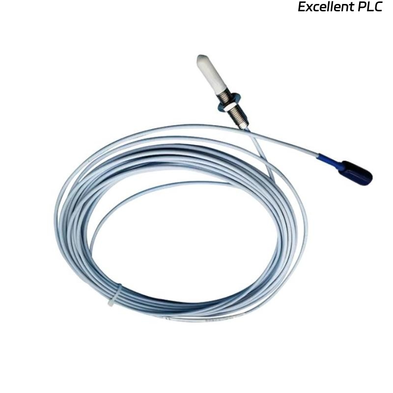
Bently Nevada 137365-01-20-02-05 Proximity Probe Installation Guide Entry
Bently Nevada 137365-01-20-02-05 proximity probe installation errors typically result in incorrect gap voltage, leading to inaccurate vibration or displacement readings rather than actual machinery faults.
This Installation Guide explains proper probe positioning, gap adjustment, and commissioning procedures to ensure reliable measurement performance.
Proximity Probe Sensor Role in Vibration Monitoring Systems
- Measures shaft displacement and vibration
- Provides input signal to monitoring modules
- Supports machinery protection and fault diagnosis
Accurate installation directly affects system reliability.
Probe Mounting Strategy and Gap Setting
Correct mechanical positioning is critical:
- Ensure probe tip is aligned with shaft surface
- Maintain proper initial gap (typically 1–2 mm depending on system)
- Avoid angular misalignment
- Ensure rigid mounting to prevent movement
Engineering Note: Even a 0.2 mm gap deviation can significantly affect signal linearity.
Cable Connection and System Configuration
- Connect probe to extension cable and proximitor module
- Ensure secure connectors and proper locking
- Route cables away from electromagnetic interference sources
- Verify grounding and shielding
Proper wiring ensures stable signal transmission.
Gap Calibration and Signal Verification
During setup and commissioning:
- Measure output voltage corresponding to probe gap
- Adjust probe position until target voltage achieved
- Verify signal stability during machine rotation
IF voltage out of range:
    adjust probe gap
    verify alignment

IF signal unstable:
    check mounting rigidity
    inspect cable shielding
Real Case: Gap Misalignment Impact
In a turbine installation, the probe output voltage was measured at -6 V instead of the expected -9 V.
Analysis:
- Sensor functioning correctly
- Mounting bracket slightly misaligned
Action:
- Re-adjusted probe position
- Corrected gap distance
Result: Voltage stabilized at -9 V, and vibration readings became consistent.
FAQ
What happens if the probe gap is incorrect?
It will produce incorrect voltage output and unreliable vibration data.
Is alignment important for proximity probes?
Yes, misalignment affects both accuracy and signal stability.
Can installation errors mimic mechanical faults?
Yes, incorrect probe setup often leads to false vibration alarms.
Technical Summary
This Installation Guide highlights that the Bently Nevada 137365-01-20-02-05 proximity probe sensor requires precise gap setting, alignment, and proper system configuration. Correct commissioning ensures accurate vibration monitoring and prevents false fault diagnosis.