

Table of Contents
- Bently Nevada 146055-05-02-05 Reverse Mount Probe Installation Guide Entry
- Reverse Mount Probe Design and Application Role
- Installation Risks of Ceramic Tip Reverse Probes
- Mechanical Installation and Orientation Control
- System Configuration and Signal Setup
- Commissioning Validation and Gap Verification
- FAQ
- Technical Summary
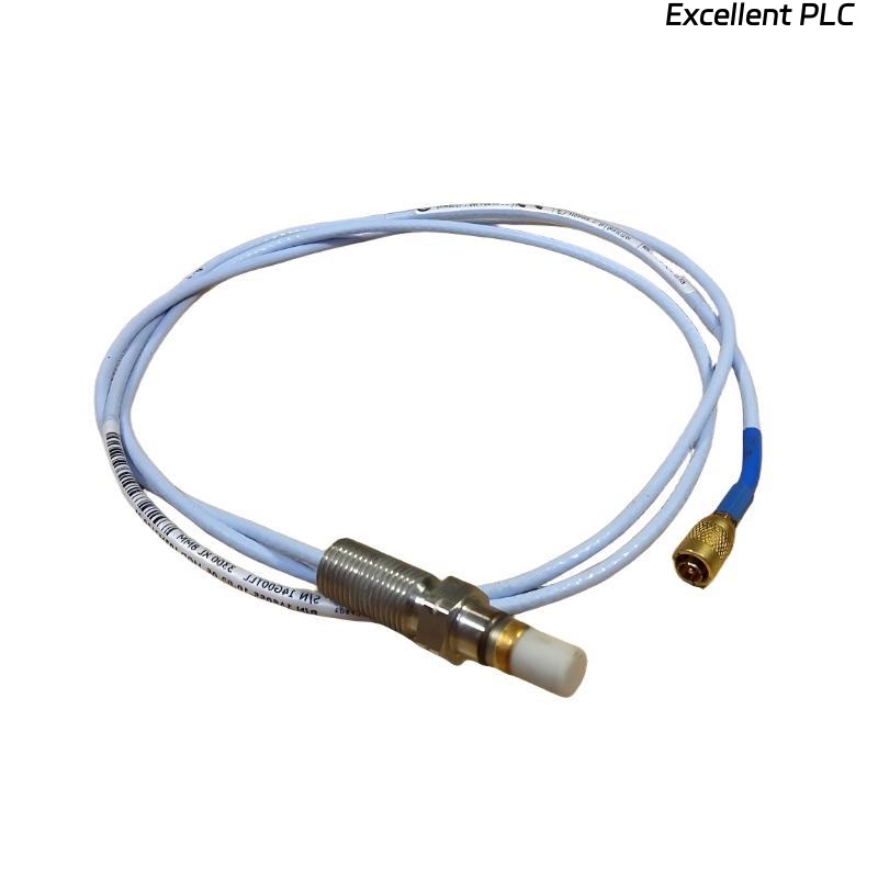
Bently Nevada 146055-05-02-05 Reverse Mount Probe Installation Guide Entry
Bently Nevada 146055-05-02-05 3300 XL reverse mount proximity probe installation errors often lead to incorrect gap voltage due to improper probe orientation rather than sensor failure.
This Installation Guide explains reverse mounting principles, ceramic tip handling, and commissioning procedures to ensure accurate displacement and vibration measurement.
Reverse Mount Probe Design and Application Role
- Designed for reverse installation in restricted mounting conditions
- Ceramic tip provides high-temperature and wear resistance
- Used in turbine, compressor, and high-speed rotating machinery
Correct orientation is critical for measurement accuracy.
Installation Risks of Ceramic Tip Reverse Probes
- Incorrect probe direction causing signal inversion
- Ceramic tip damage during installation
- Improper gap setting due to reverse geometry
- Mechanical stress from incorrect mounting angle
Field Insight: Reverse probes require more precise positioning compared to standard probes.
Mechanical Installation and Orientation Control
- Identify correct mounting direction based on machine design
- Carefully install probe without applying lateral force
- Ensure ceramic tip faces target surface correctly
- Secure mounting with proper torque
Avoid any impact or bending force on the ceramic tip.
System Configuration and Signal Setup
- Connect probe to extension cable and proximitor
- Verify compatibility with 3300 XL system
- Ensure proper shielding and grounding
Correct configuration ensures stable signal transmission.
Commissioning Validation and Gap Verification
During setup and commissioning:
- Measure probe output voltage (typically -8V to -10V range)
- Adjust probe position to achieve correct gap
- Verify signal stability under operating conditions
IF voltage incorrect:
    verify probe orientation
    adjust gap distance

IF signal unstable:
    inspect mounting rigidity
    check cable integrity
Real Case:
In a steam turbine system, probe voltage was unstable at -5V. Investigation showed reversed installation orientation. After correction, voltage stabilized at -9V and vibration signal normalized.
FAQ
What is the main difference of reverse mount probes?
They are designed for installation from the opposite direction compared to standard probes.
Can ceramic tips be damaged easily?
Yes, improper handling or excessive force can damage the ceramic tip.
Why is gap adjustment more difficult?
Reverse geometry makes visual and mechanical alignment more challenging.
Technical Summary
This Installation Guide highlights that Bently Nevada 146055-05-02-05 reverse mount proximity probes require careful orientation control, precise gap adjustment, and proper commissioning. Correct installation ensures accurate measurement and long-term reliability in harsh environments.