

Table of Contents
- Bently Nevada 148638-02 Serial Cable Installation Guide Entry
- Serial Cable Role in Monitoring System Communication
- Installation Constraints and Signal Risks
- Cable Connection and Interface Configuration
- System Setup and Communication Commissioning
- Signal Verification and Data Integrity Check
- FAQ
- Technical Summary
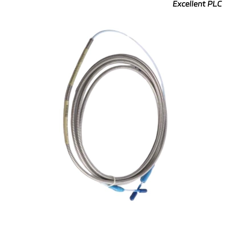
Bently Nevada 148638-02 Serial Cable Installation Guide Entry
Bently Nevada 148638-02 serial cable communication failure during installation is commonly caused by incorrect wiring configuration or grounding issues rather than cable defects.
This Installation Guide focuses on communication integrity, correct interface matching, and commissioning procedures for reliable data transmission.
Serial Cable Role in Monitoring System Communication
- Provides serial communication between monitoring modules and host systems
- Supports configuration, diagnostics, and real-time data transmission
- Typically used in rack-based condition monitoring systems
Reliable communication depends heavily on correct installation practices.
Installation Constraints and Signal Risks
- Signal interference from nearby power cables
- Ground loop issues affecting communication stability
- Incorrect pin configuration (TX/RX mismatch)
- Excessive cable length causing signal attenuation
Engineering Note: Serial communication is sensitive to noise and grounding quality.
Cable Connection and Interface Configuration
- Identify correct communication ports (RS232 / RS485)
- Verify pin assignments before connection
- Ensure connectors are firmly seated
- Apply proper shielding and grounding
Always follow system wiring diagrams during setup.
System Setup and Communication Commissioning
- Configure baud rate, parity, and stop bits
- Match communication parameters between devices
- Test communication using diagnostic tools
IF no communication:
    verify TX/RX wiring
    check baud rate settings

IF unstable communication:
    inspect grounding
    reduce cable interference

IF intermittent data:
    check connector integrity
    verify cable routing
Real Case:
During commissioning of a turbine monitoring system, no communication was detected. Investigation revealed TX and RX lines were reversed. After correction, communication was established immediately with stable data transfer.
Signal Verification and Data Integrity Check
- Confirm stable data transmission over time
- Check for packet loss or communication errors
- Validate system configuration parameters
Stable communication confirms successful installation.
FAQ
What causes serial communication failure most often?
Incorrect wiring and mismatched communication settings are the most common causes.
Can cable routing affect communication?
Yes, routing near high-power lines can introduce interference.
How to verify correct configuration?
Use diagnostic software to monitor communication status and data flow.
Technical Summary
This Installation Guide explains that Bently Nevada 148638-02 serial cable performance depends on correct wiring, proper grounding, and accurate system configuration. Careful commissioning ensures stable and reliable communication in monitoring systems.