

Table of Contents
- Bently Nevada 151M8244-01 Accelerometer Cable Installation Guide Entry
- Role of Accelerometer Cable in Sensor Signal Transmission
- Environmental and Routing Considerations for Installation
- Cable Wiring and Shielding Configuration
- System Configuration and Signal Integration
- Commissioning and Signal Validation
- FAQ
- Technical Summary
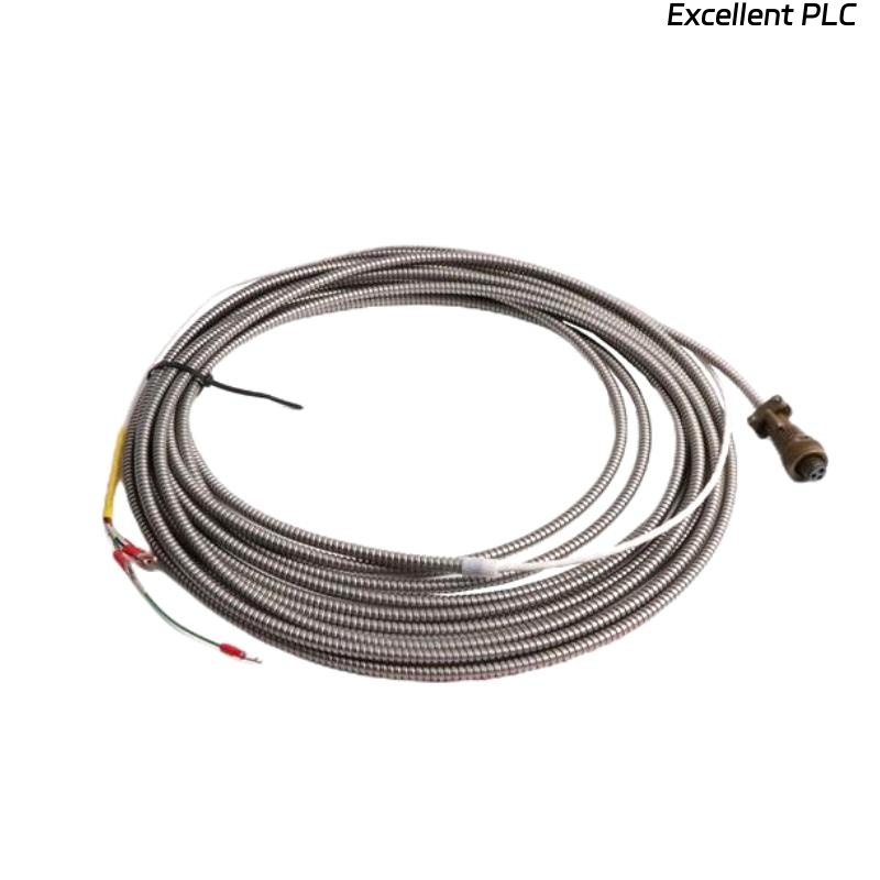
Bently Nevada 151M8244-01 Accelerometer Cable Installation Guide Entry
Bently Nevada 151M8244-01 accelerometer cable installation errors frequently result in noisy vibration signals due to improper shielding or incorrect routing rather than sensor malfunction.
This Installation Guide explains practical wiring strategies, grounding methods, and commissioning checks to ensure accurate vibration signal transmission.
Role of Accelerometer Cable in Sensor Signal Transmission
- Transfers low-level vibration signals from accelerometer to monitoring module
- Maintains signal integrity under industrial noise conditions
- Provides shielding against electromagnetic interference
The cable quality and installation directly affect measurement accuracy.
Environmental and Routing Considerations for Installation
- Route cable away from high-voltage and motor power lines
- Avoid sharp bends and mechanical stress
- Protect from high temperature zones (>80°C where possible)
- Use conduit or cable trays for mechanical protection
Field Experience: Signal noise often correlates with poor cable routing near VFD-driven motors.
Cable Wiring and Shielding Configuration
- Connect accelerometer output to monitoring module input
- Ensure shield grounding at one end only (typically module side)
- Avoid ground loops by isolating sensor ground
- Secure connectors firmly to prevent loosening
Improper shielding is a primary cause of signal instability.
System Configuration and Signal Integration
- Verify input channel configuration (IEPE / charge type)
- Check signal scaling parameters in monitoring system
- Confirm compatibility with vibration module
IF signal noisy:
    check shielding connection
    inspect cable routing

IF no signal:
    verify wiring continuity
    check connector integrity

IF unstable reading:
    inspect grounding scheme
    check mechanical stress points
Real Case:
During commissioning of a pump monitoring system, vibration readings fluctuated between 2 mm/s and 10 mm/s. Investigation showed cable routed alongside inverter power cables. After rerouting and improving shielding, readings stabilized at 3 mm/s.
Commissioning and Signal Validation
- Measure baseline vibration levels
- Verify signal consistency over time
- Compare readings with reference instruments
Stable readings confirm successful installation.
FAQ
Why is shielding grounding only on one side?
This prevents ground loops that introduce signal noise.
Can cable length affect signal quality?
Yes, excessive length can reduce signal strength and increase noise.
What is the most common installation mistake?
Routing cable near power lines without proper shielding.
Technical Summary
This Installation Guide shows that Bently Nevada 151M8244-01 accelerometer cable performance depends on correct routing, proper shielding, and accurate system configuration. Careful installation ensures reliable vibration monitoring results.